Singapore Robotic Games 2020
After the not so successful run last year, I started planning for another run. The biggest issue was my choice of tracks, which offered close to no traction. The other problem was the weight of the drive system - being nearly 2kg, there was very little left for other components.
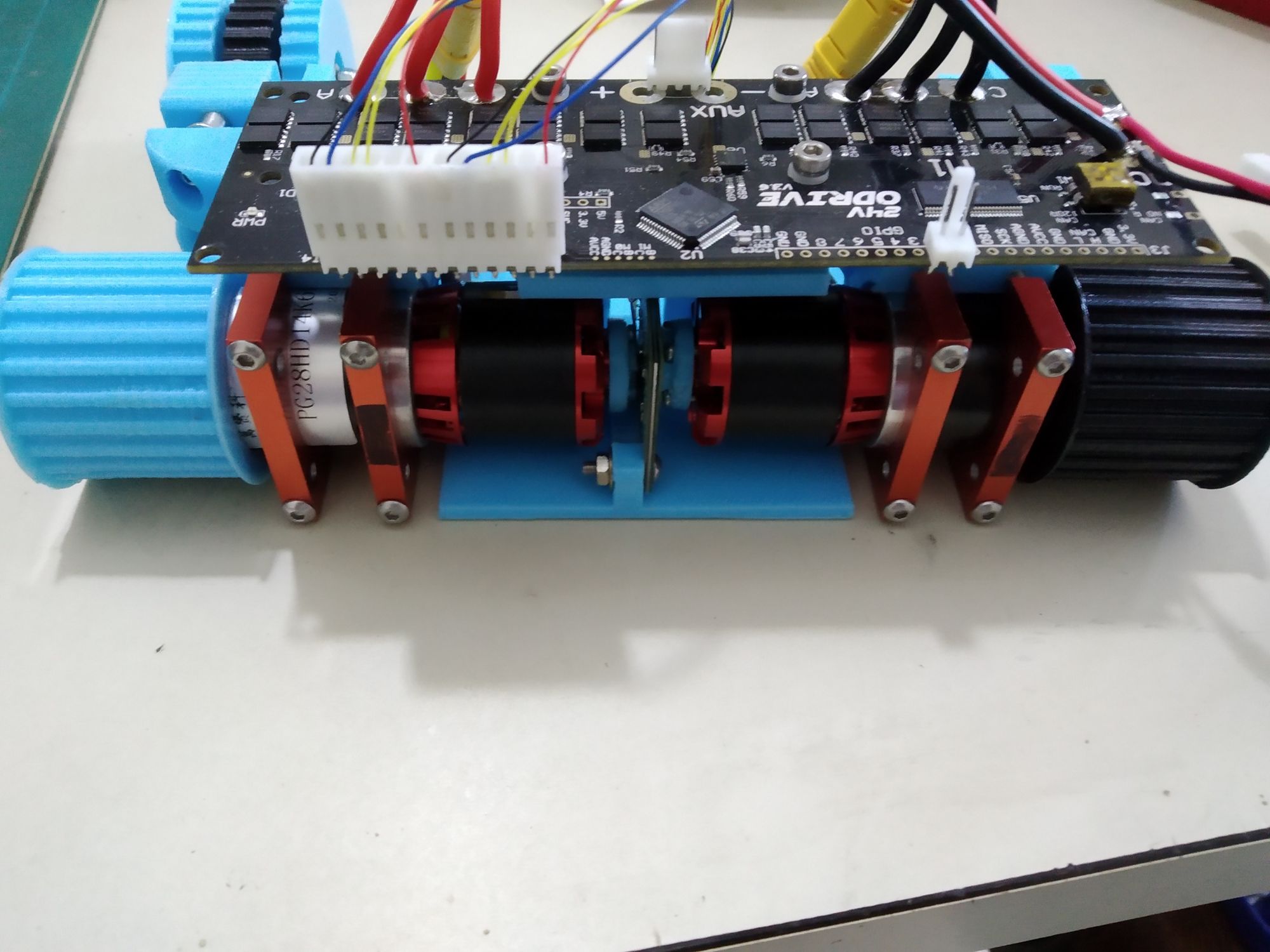
Drive
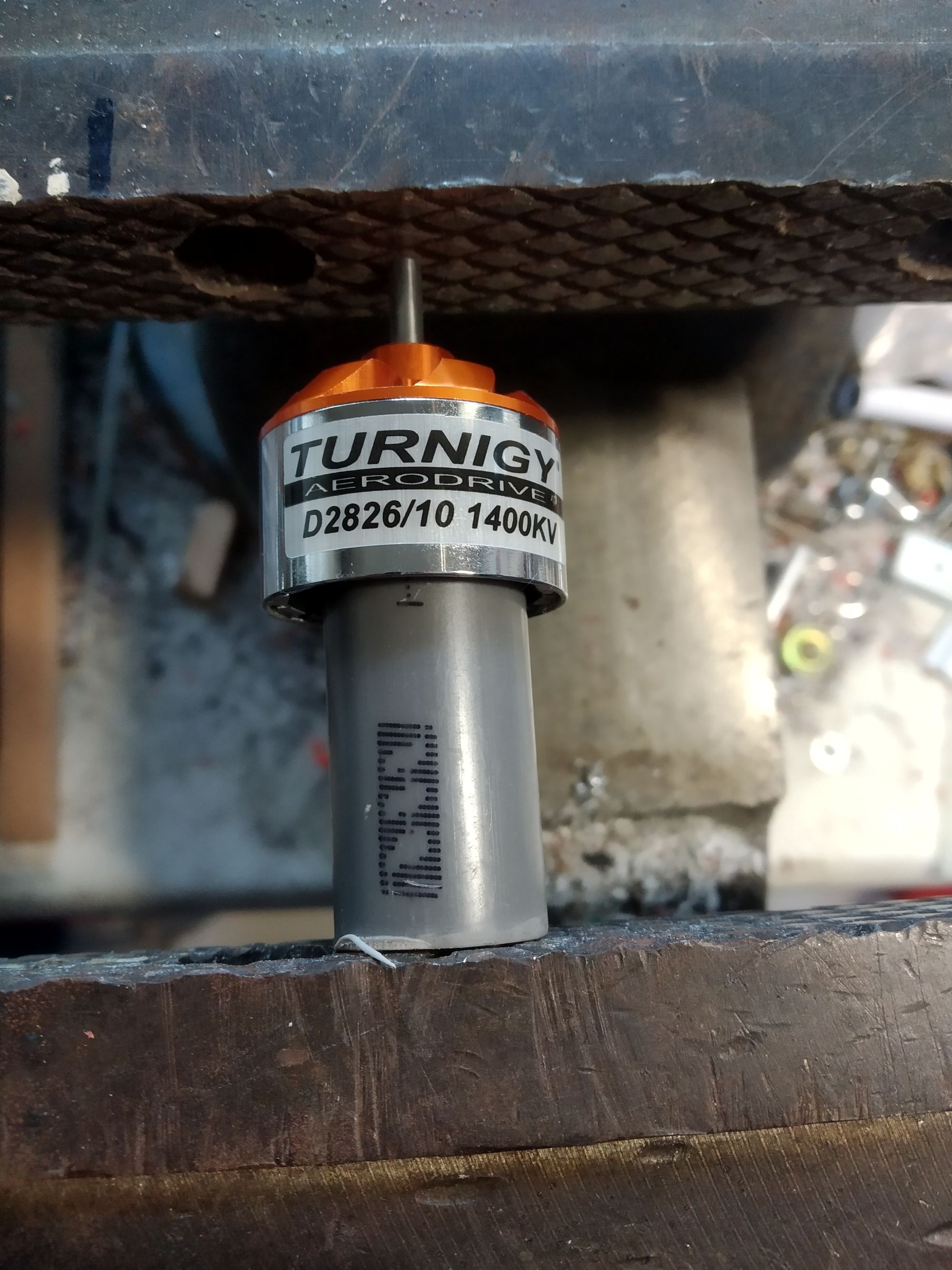
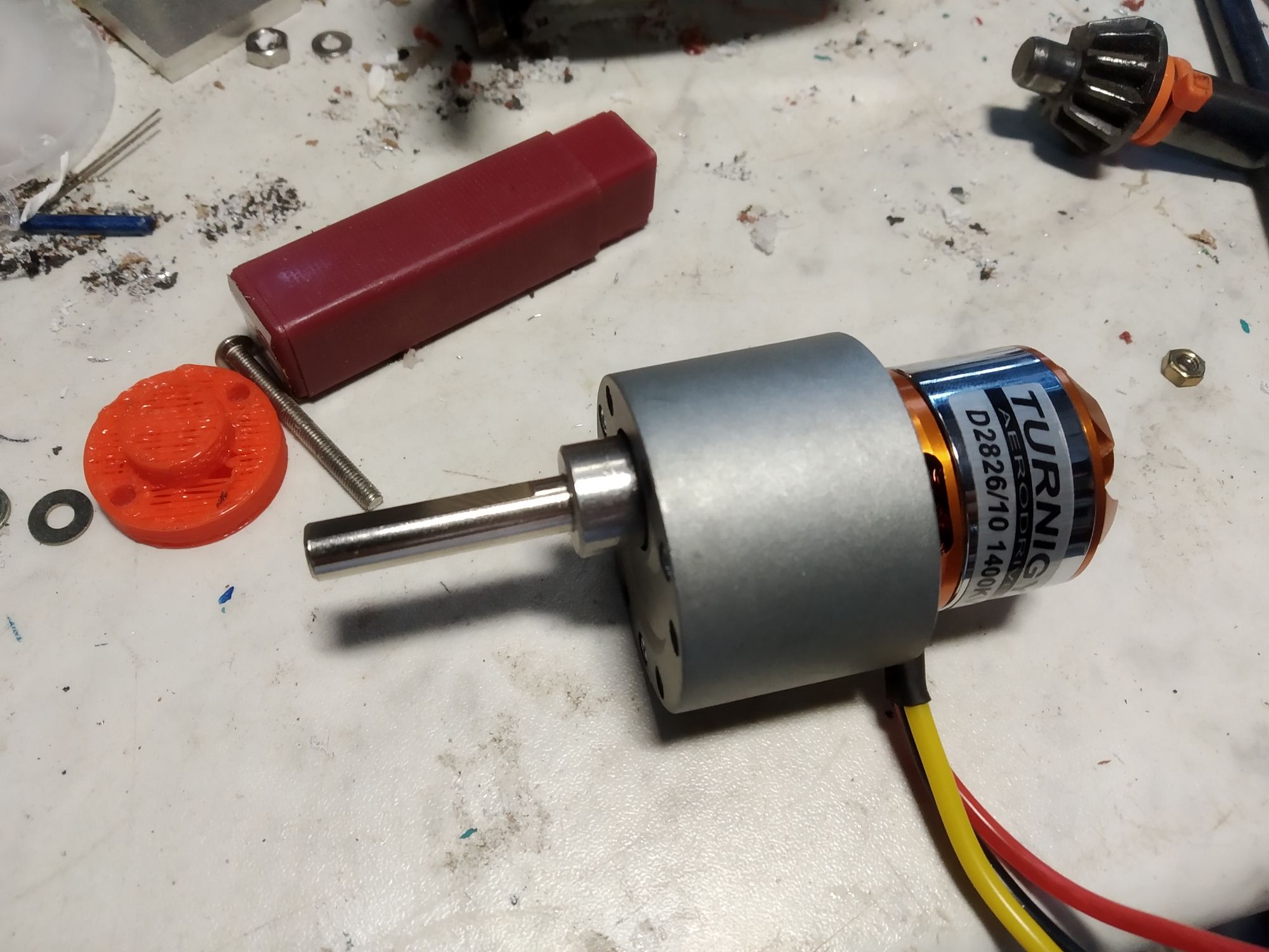
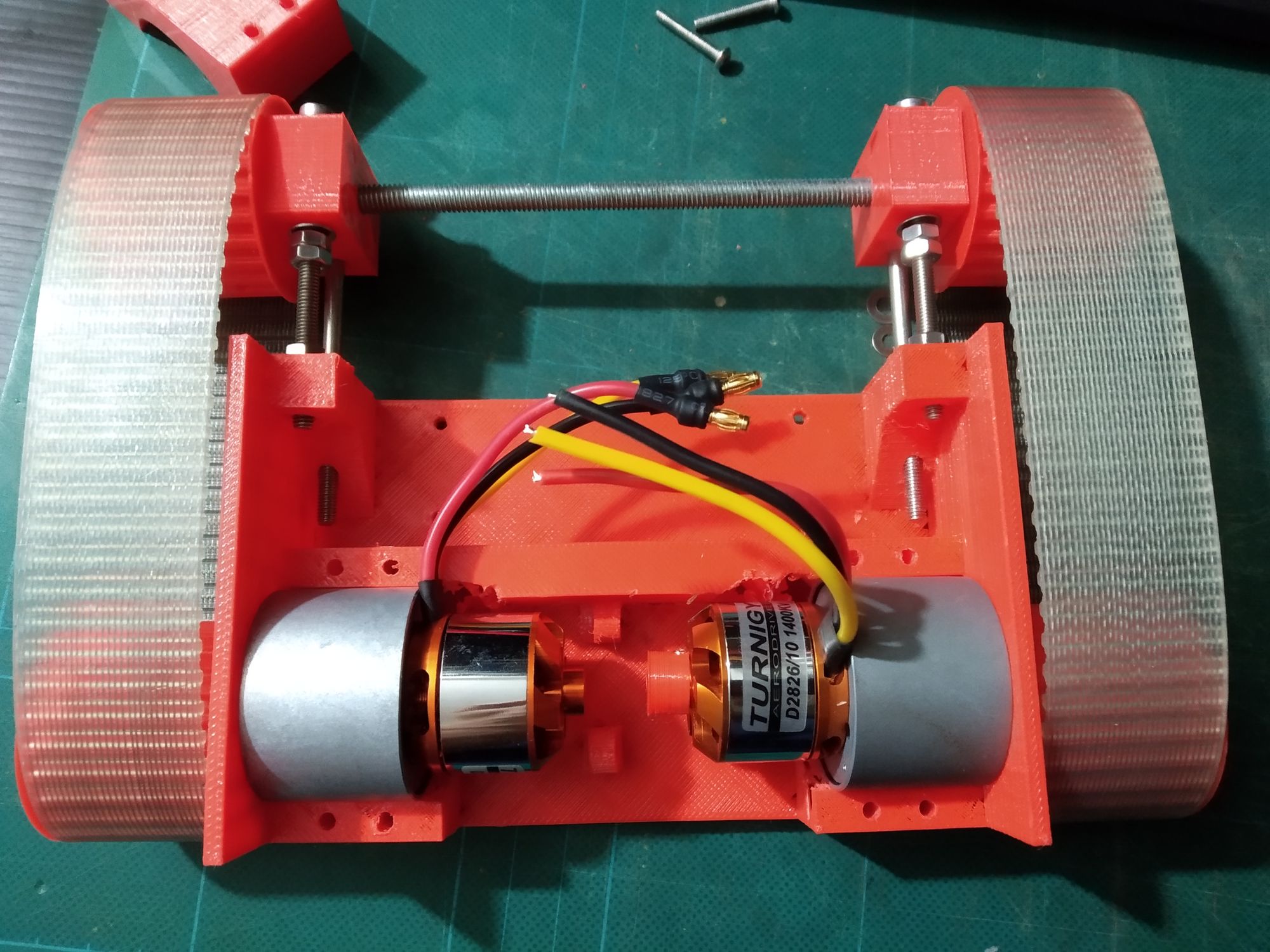
Small 2826 brushless RC motors were mated to Neverest 40 gearboxes. Sadly, the mounting holes on the motor (16/19mm) and the mounting holes on the gearbox (25mm) did not match. However, some of the support structure could be milled away to drill holes to match the 19mm mounting holes.
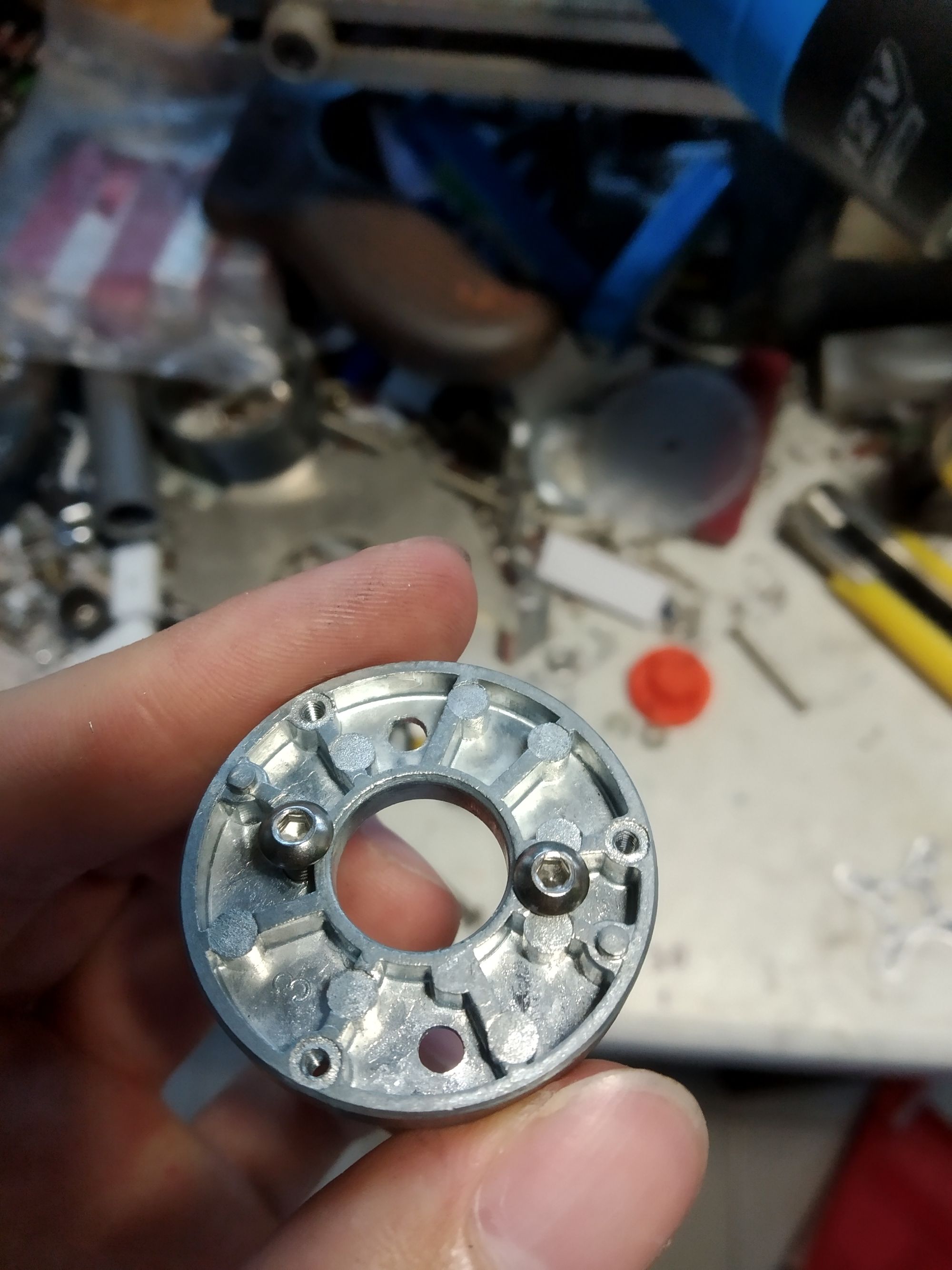
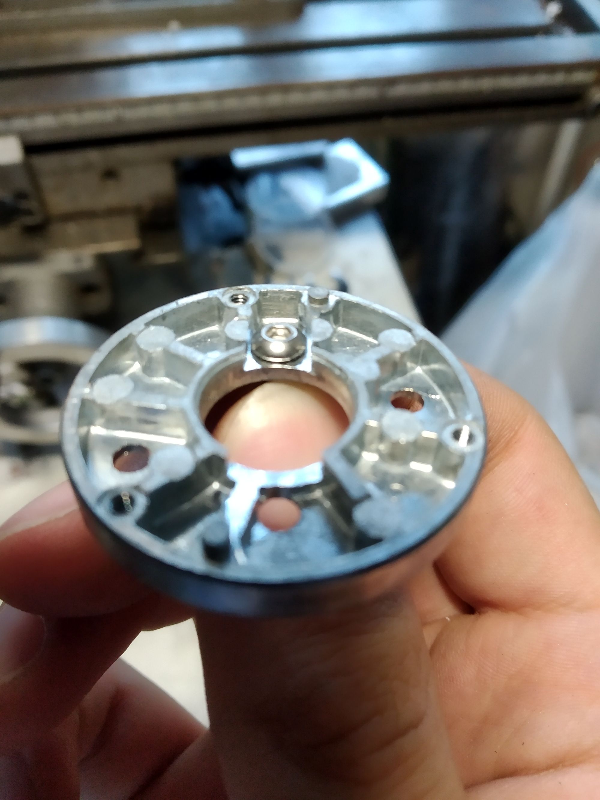
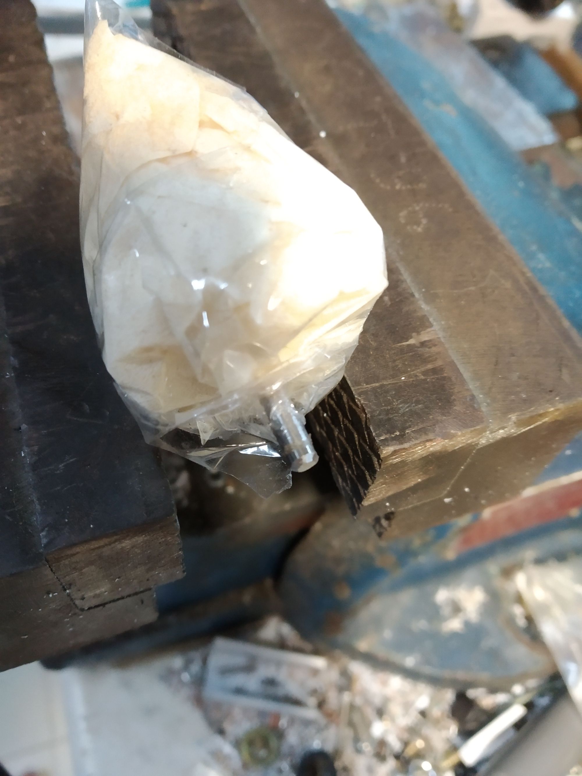
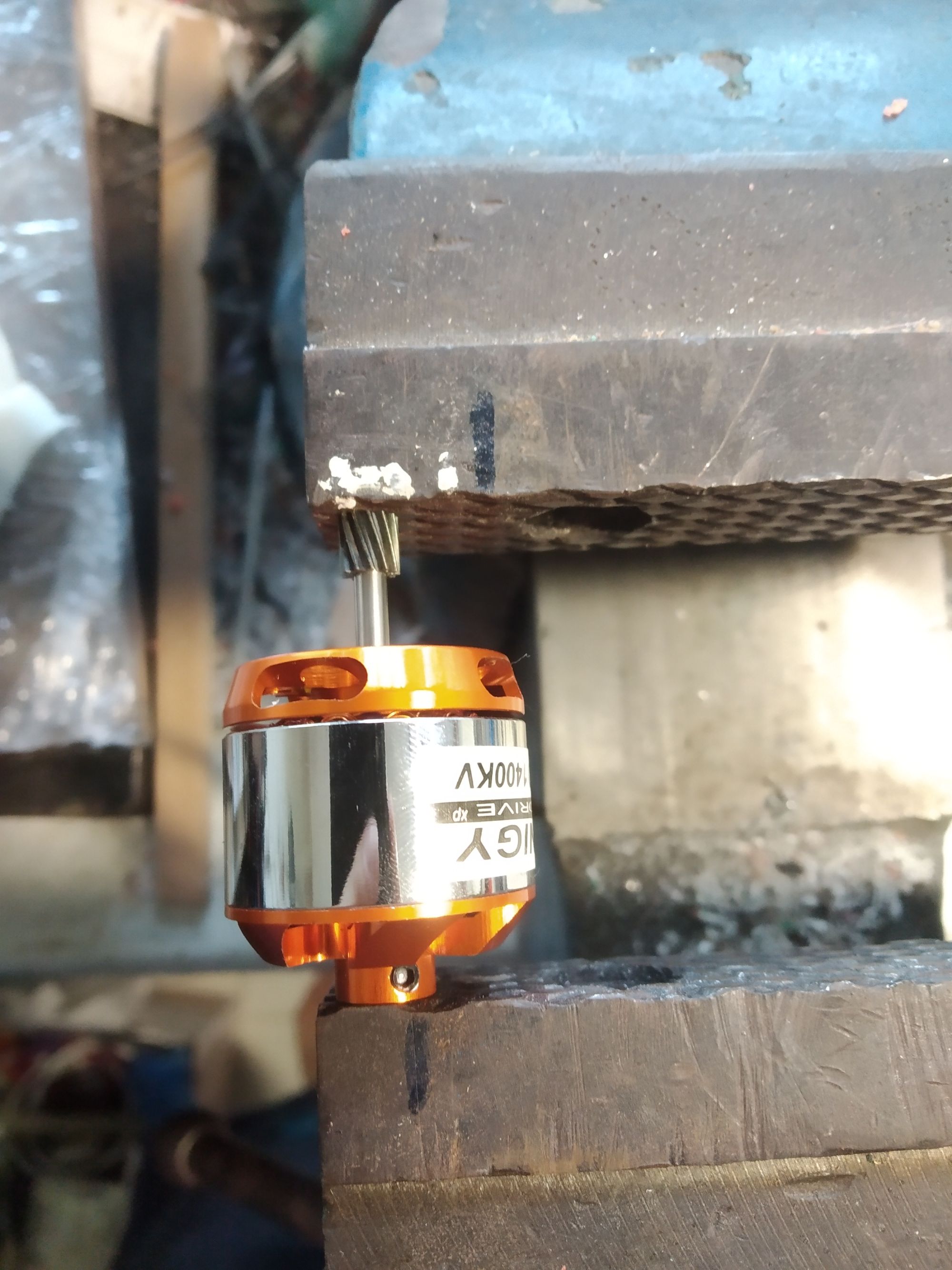
There were 2 issues with the motor shaft:
- It was a few mm too long
- It was on the wrong side
Side Experiment
Making a assumption (wrong) that I coudn't source a small vacuum cleaner, I tried to build my own: it ended as well as you'ld expect:
Motor Driver
Using standard ESCs for quadcopters is most obvious choice, but there was one critical issue here: these drive the motors using sensorless control, which is perfectly fine for quadcopters (propeller can always turn freely), but not so fine for use in robotics where the robot might have to start moving against a load (eg pushing another robot from a dead stop).
With that in mind, sensored control was the only option. There were a few choices here:
- VESC: meant for skateboards, relatively higher power. Size and cost however made me look around for other options.
- ST's B-G431B-ESC1: relatively new, fits the requirements well except that I didn't want to tangle with a STM32 just yet (My understand is that I have to write my own firmware to control the motor from the communication buses)
- ODrive: final option, cost per axis and software support looked good. As a plus point, it was designed for robotics in mind and had quite a bit of documentation around
With that, I decided on the ODrive.
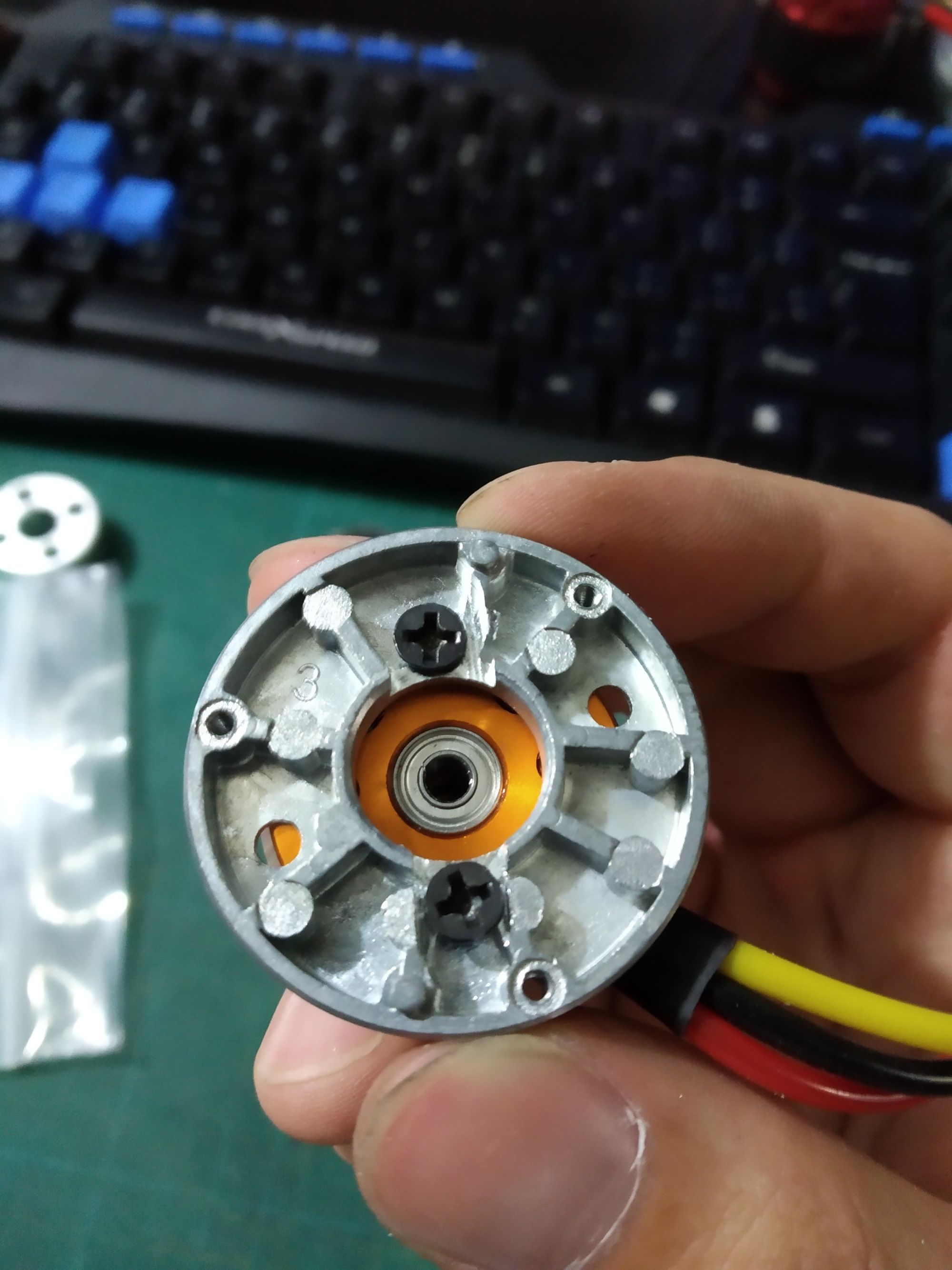
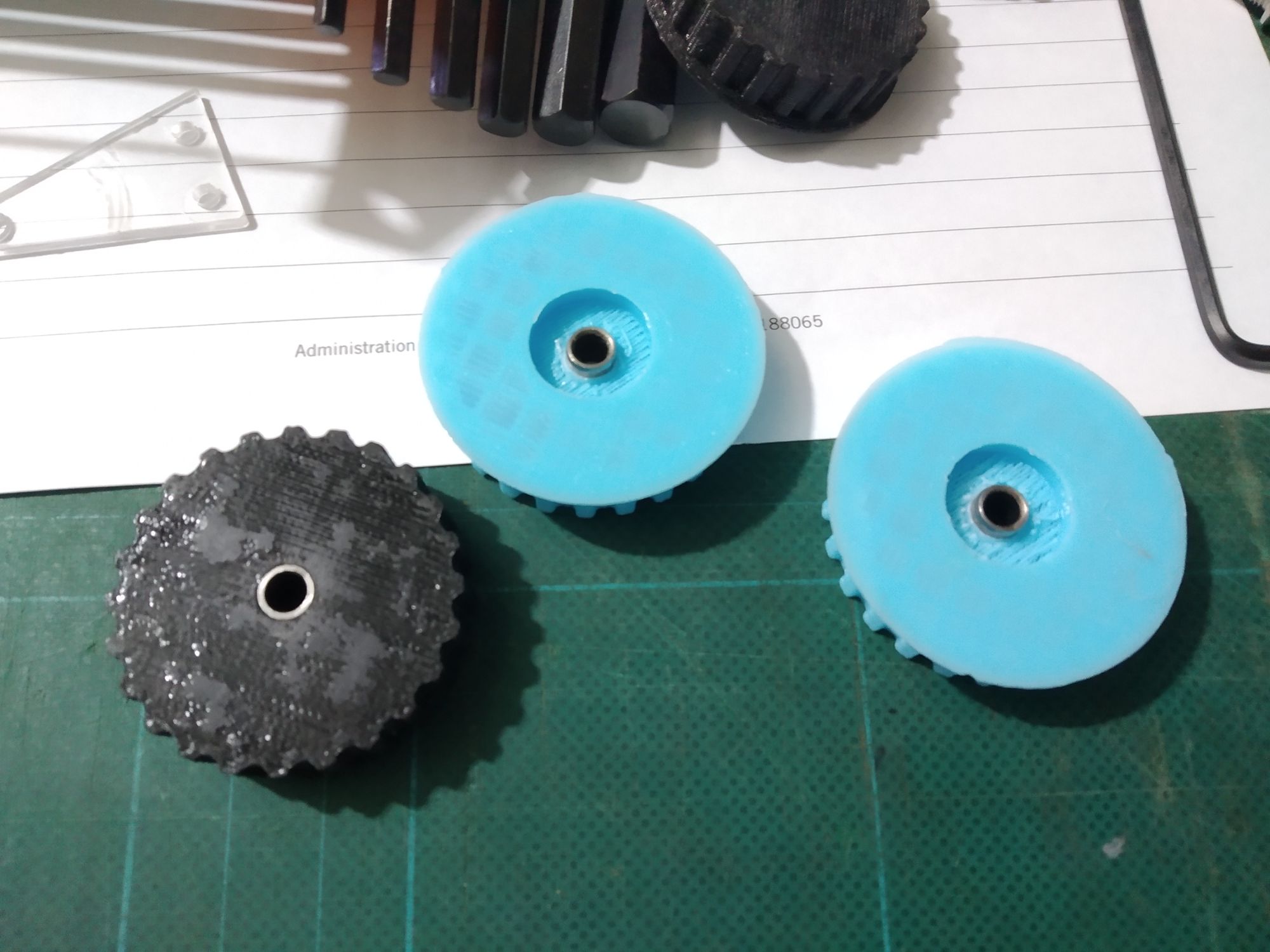
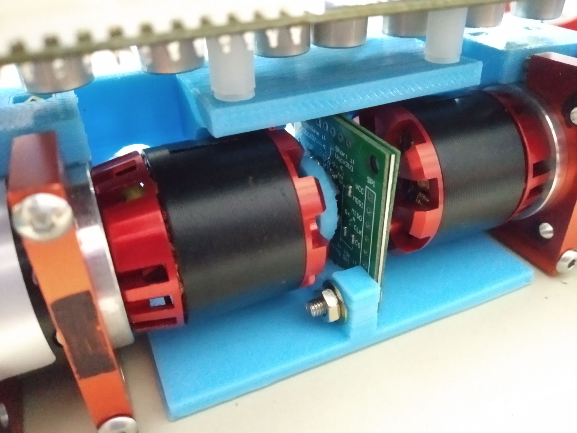
Sensors
Since the brushless motors did not come with sensors, a diametrically magnetised magnet was attached to the back of the motor. This, along with a AS5047P, allowed the ODrive to control the motor using sensored control.
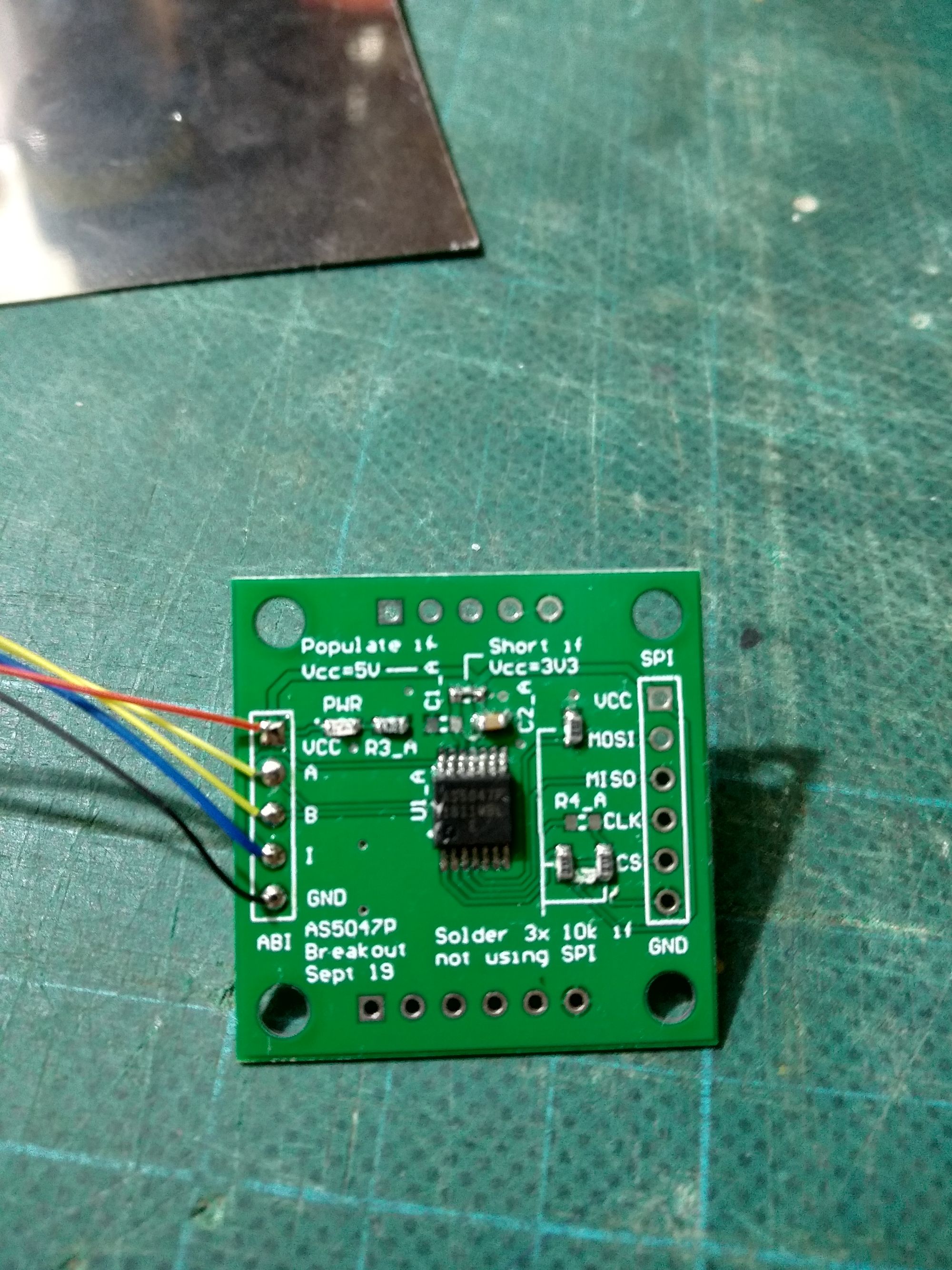
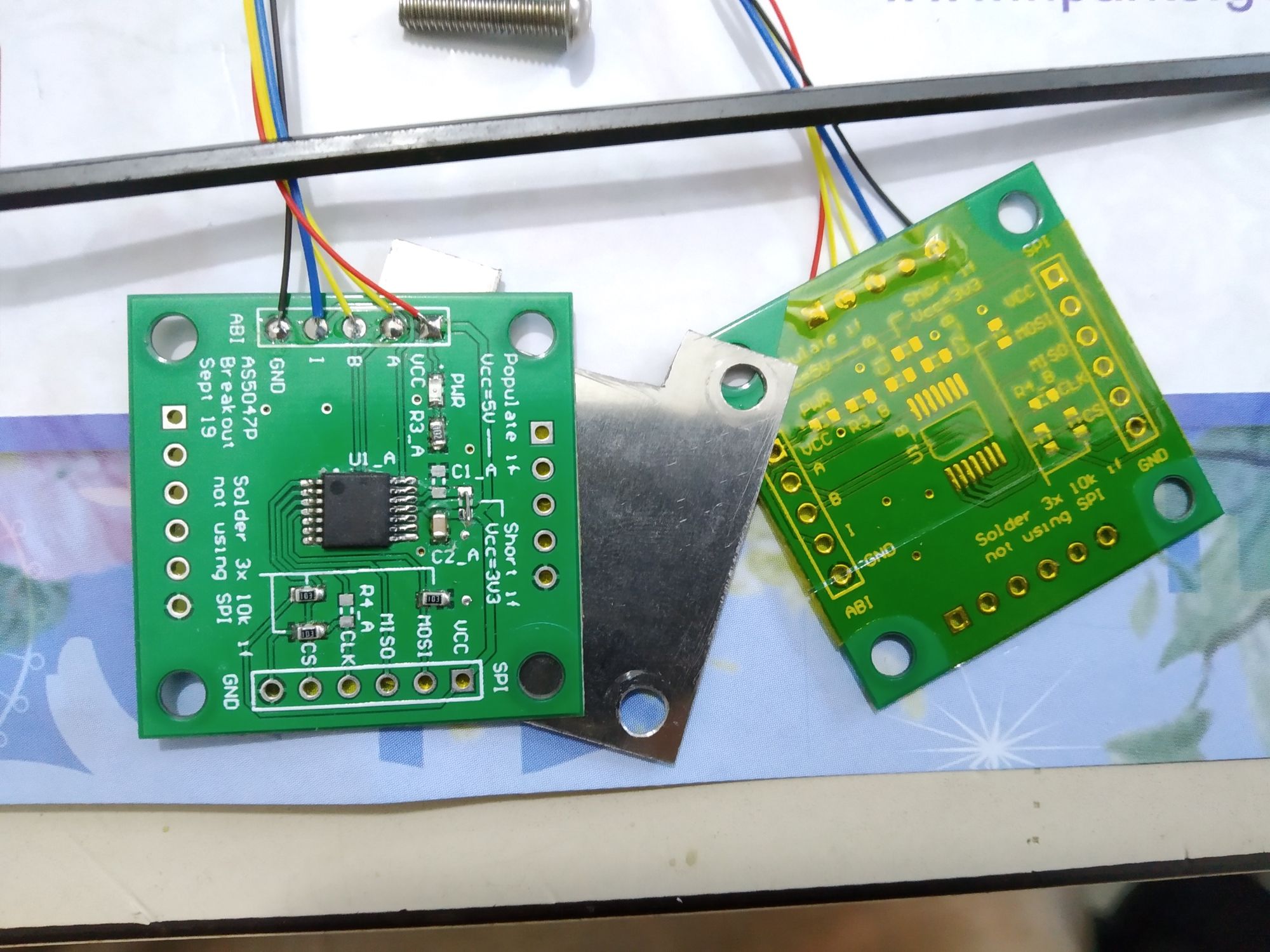
The breakout boards were designed to allow two AS5047P to be mounted on each side, one for each motor. However, I realised that the magnets could interfere with the encoder on the opposite side, so a thin magnetic plate was sandwiched between two separate PCBs.
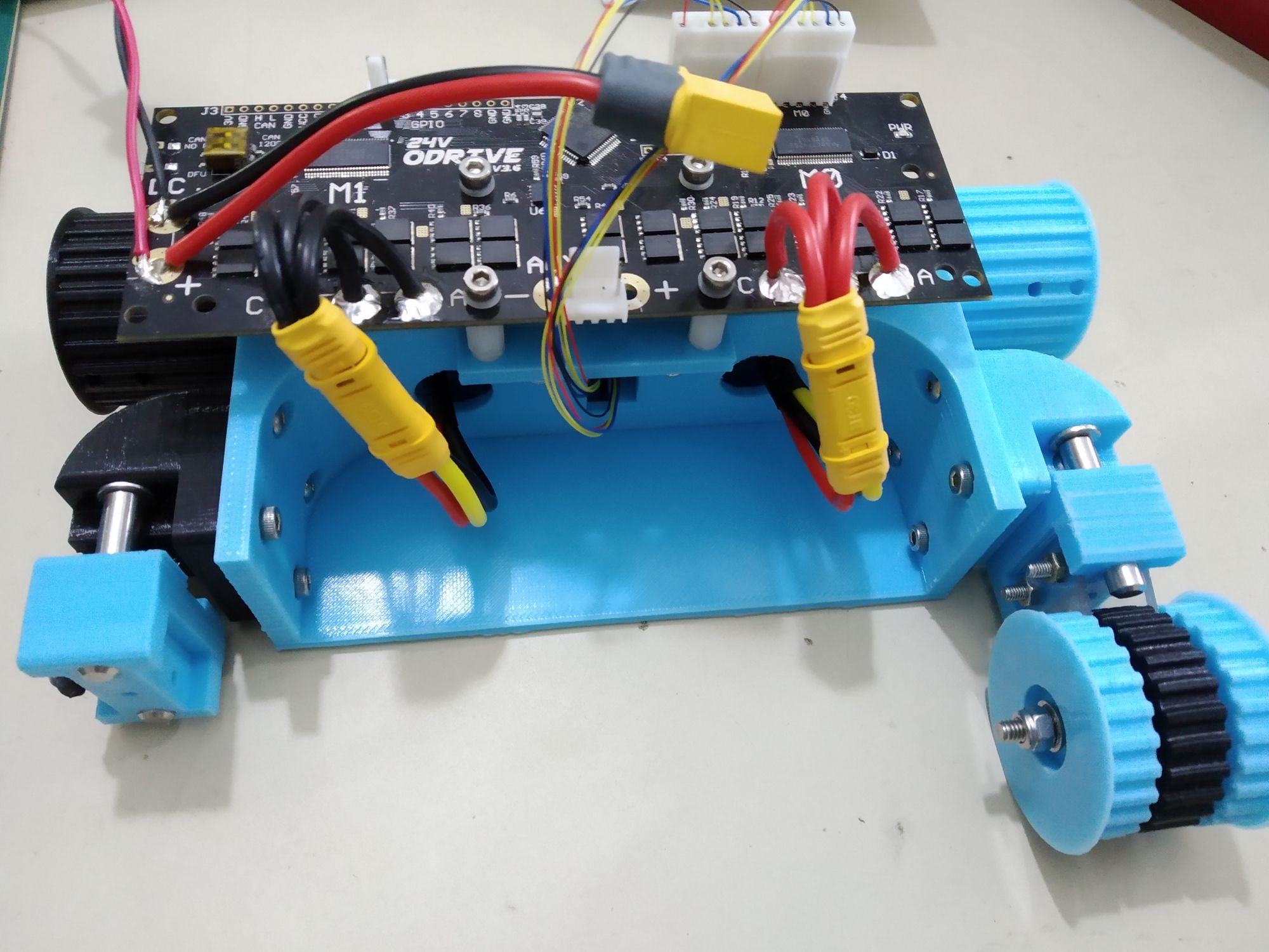
Chassis
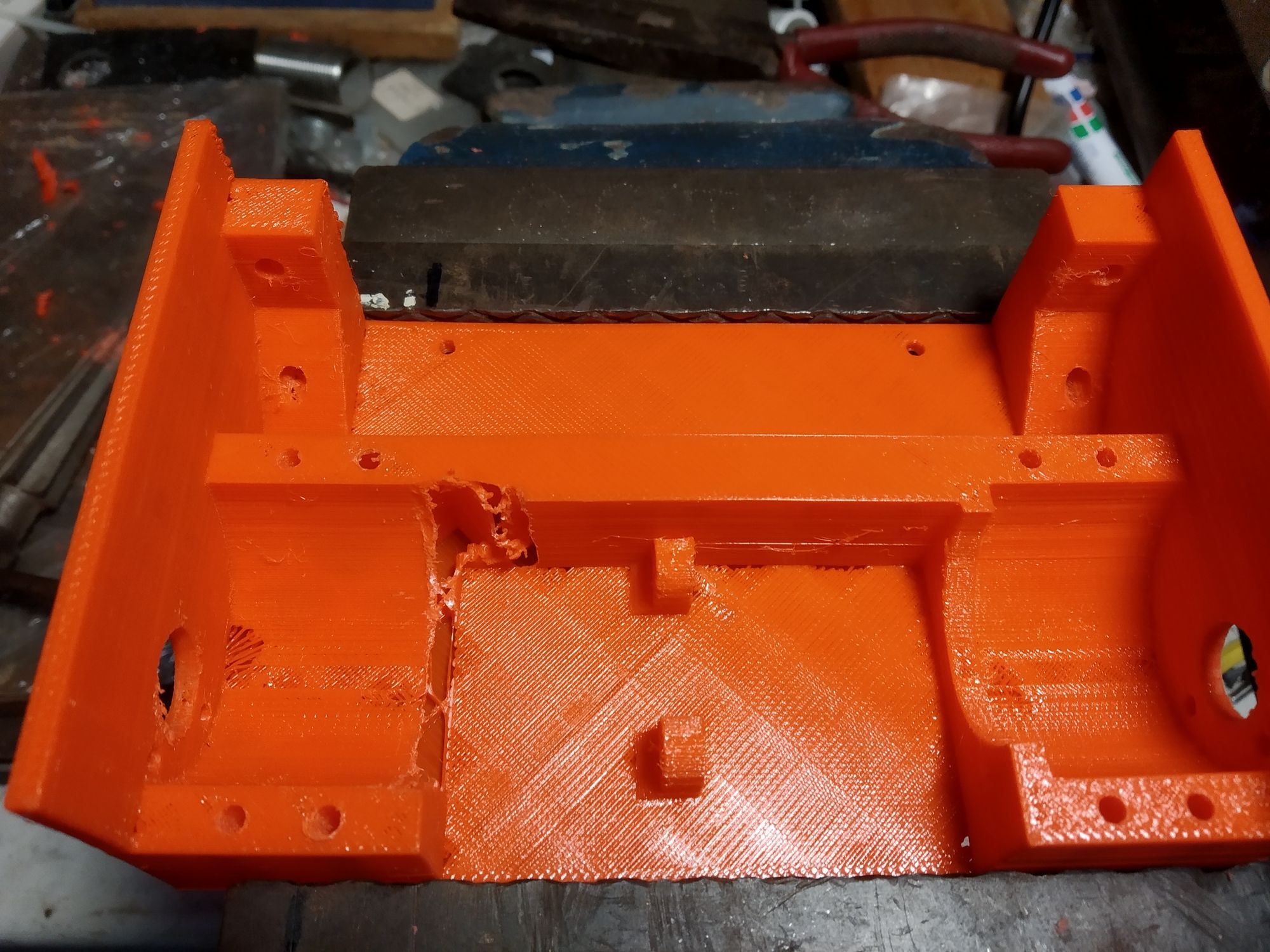
A chassis was modeled and printed. Driving this around made me realise that the current setup was too slow, the maximum theoretical speed was around 440cm/s. Back to the drawing board.
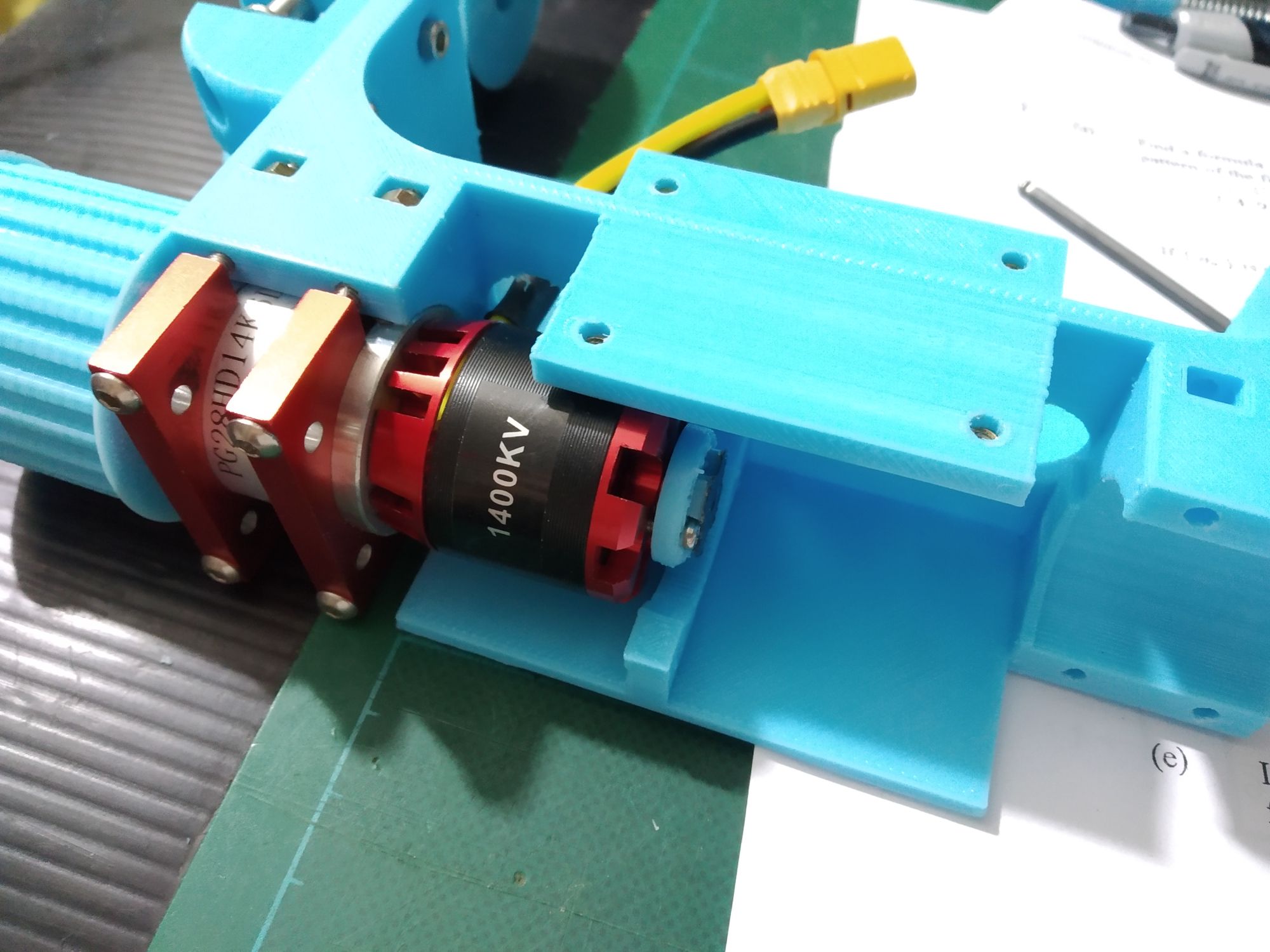
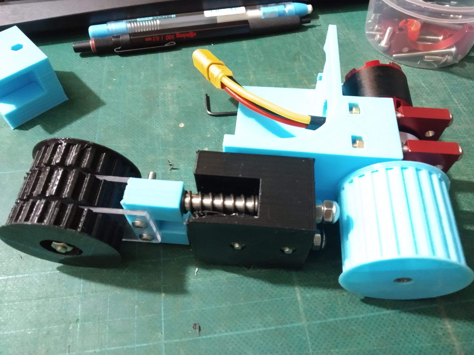
Rather than stick to the existing spur gear Neverest gearboxes which required custom machining, I switched to using 28mm planetary gearboxes from TaoBao. These had a larger range of ratios and pinion gear shaft diameters available. Even better, the mounting holes on these gearbox actually match the 16/19mm holes on the new motors.
Note the change to the nice aluminium clamps to hold the gearbox - the printed clamps were prone to cracking if over tightened.
Track Tensioner
At this state, the drive system has been limited to the rear of the robot and I wanted to keep the front free for other systems. This meant eliminating the threaded rod that I used to connect the two front pulleys together. However, the current use of screws to tension the tracks requires that the two front pulleys are attached together (or else the pulleys would not stay parallel).
The first idea I had was to use springs to tension the pulleys - theoretically, I could push the pulleys together, slip the belt over, then release the pulleys. The springs would then tension the tracks. However, practically, I found that it was hard to strike a balance on spring tension - too little and the track did not get tensioned fully, too much and it was impossible to compress the springs by hand.
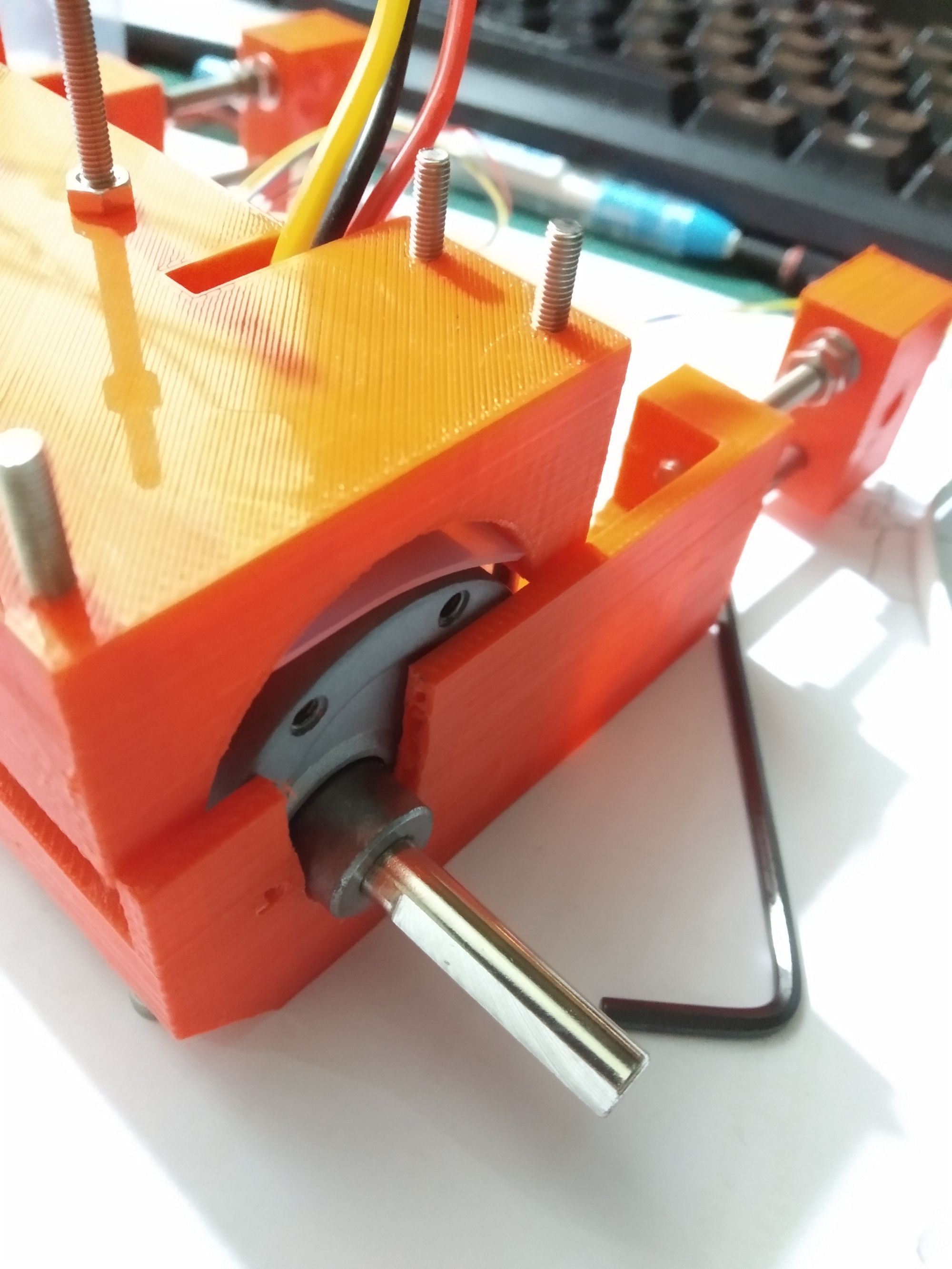
Not being able to adapt an existing design to tension the tracks, I took inspiration from Cam Clamps and used a cam to tension the tracks. The cam could be moved to either tension the track (left) or release the track (right)
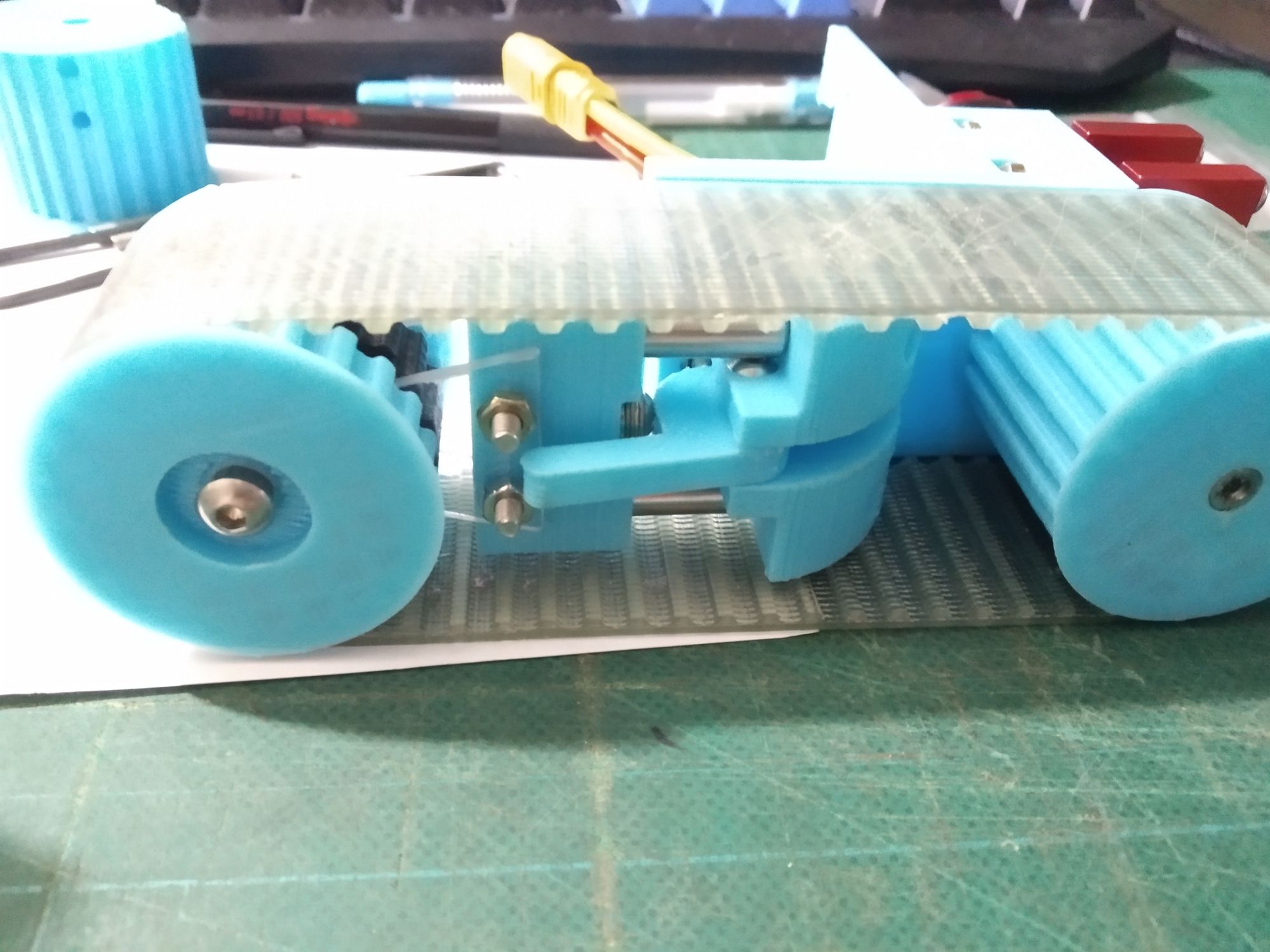
A little bit of extra work was needed to get the tensioner to work - the front pulley had to be split into 3 parts so that the cam could push against it.
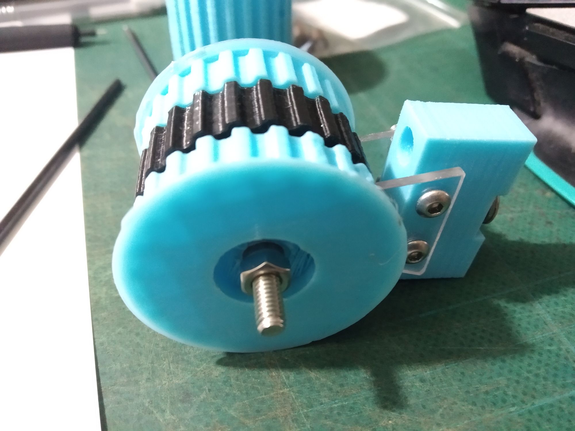
Bushings were added to the front pulley after the PLA around the screw melted due to friction (of PLA directly against screw thread).
Tracks
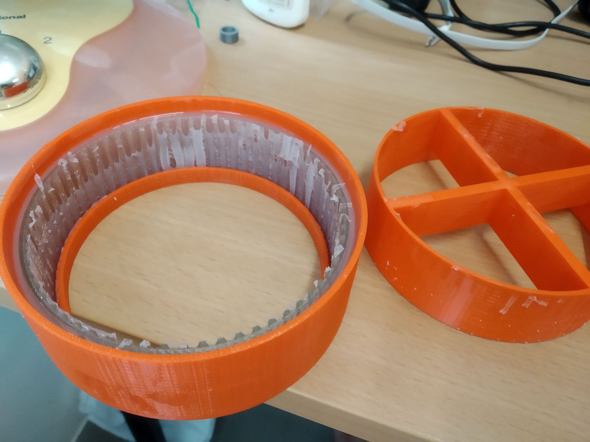
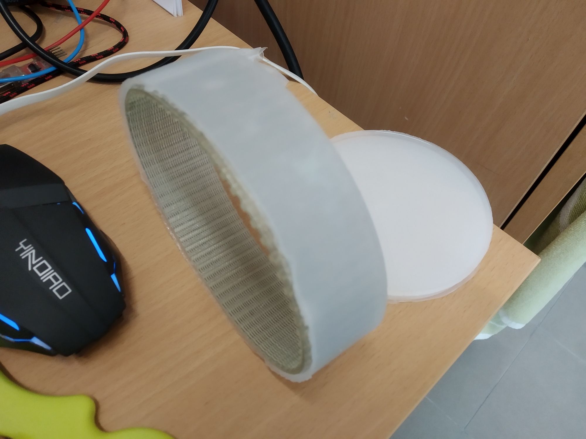
Not being able to source tracks/belts meant for high traction, I decided to cast my own with silicone. The tracks were cast around the belt in a 2 part printed mould.
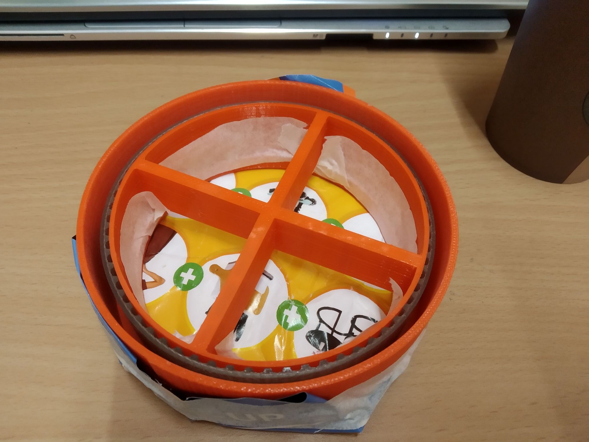
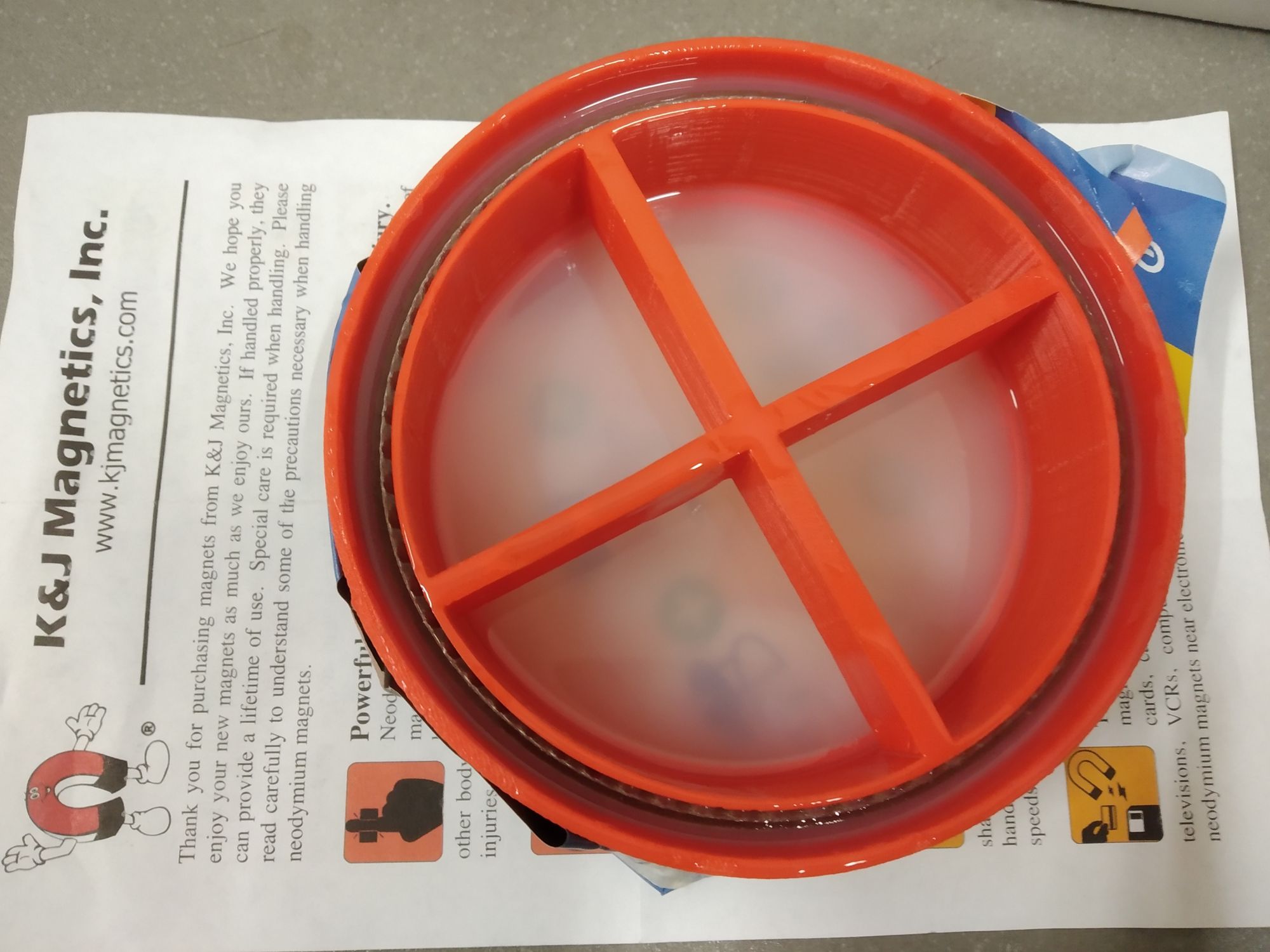
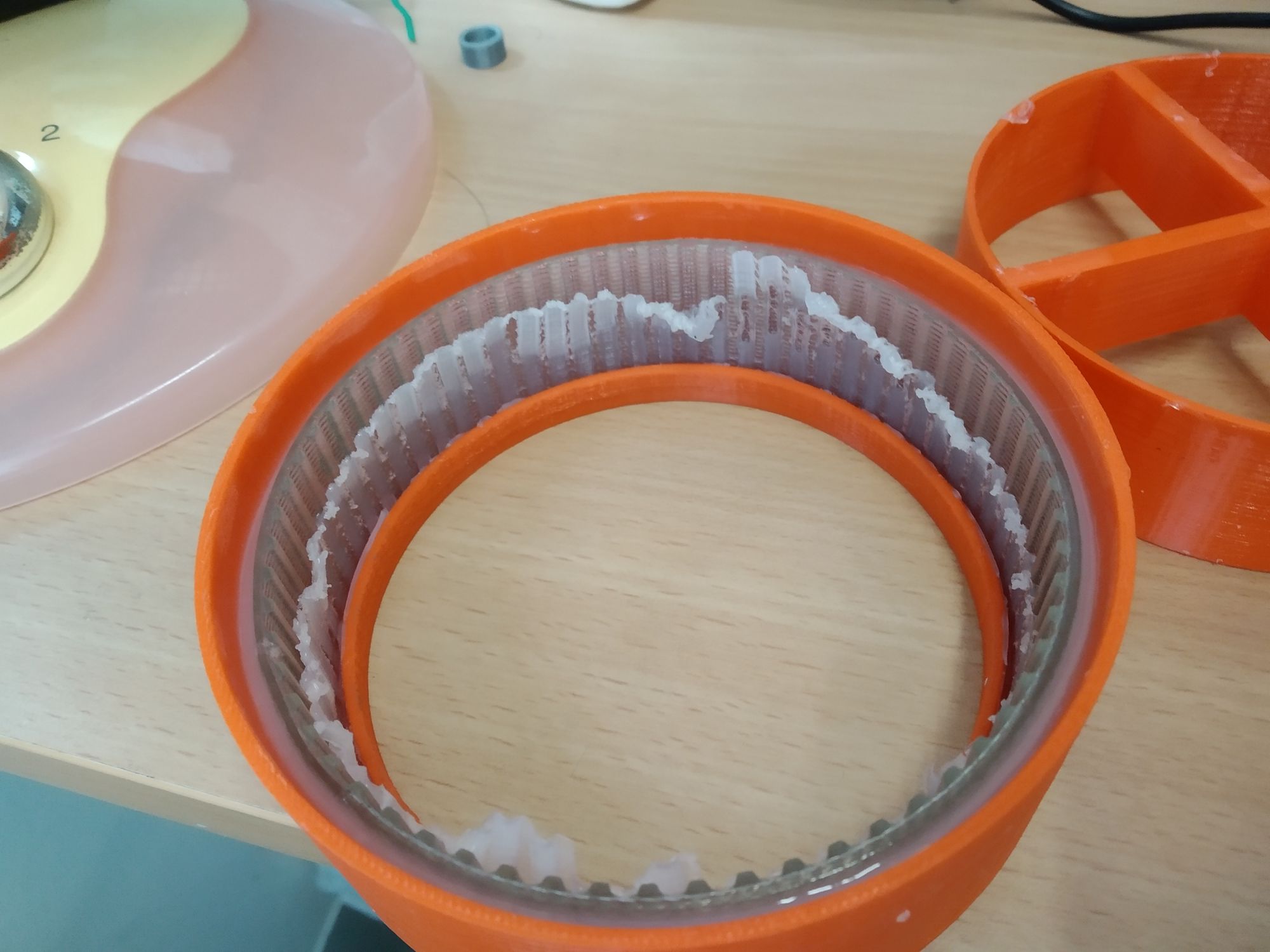
The silicone tracks were then glued to the belts using standard silicone sealant (which failed over time, the sealant did not stick to the belt surface).
There were a couple of learning points here:
- Imperfections in the mould (eg layer lines from printing) transferred very well to the resulting track, requiring extensive sanding to remove the lines before casting
- The silicone is picky about what kind of surfaces it comes in contact with during the curing process. Spraying the mould with lacquer actually caused the resulting silicone casting to shrink
The casted tracks were also sticky, which I initially attributed to cure inhibition (which had no clear cause, using the same mould sometimes resulted in very sticky tracks. Maybe the mix ratio was not perfectly 1:1?). Sprinkling on some talcum powder helped to minimise the stickiness.
Annoyingly, the tracks left residue on the floor. This residue was slippery and could not be cleaned off with standard soap/alcohol.
Eventually, I switched from the initial Shore 0A (E600) silicone to Shore 10A (E610) which mostly resolved the issue of sticky tracks, but still left residue on the floor.
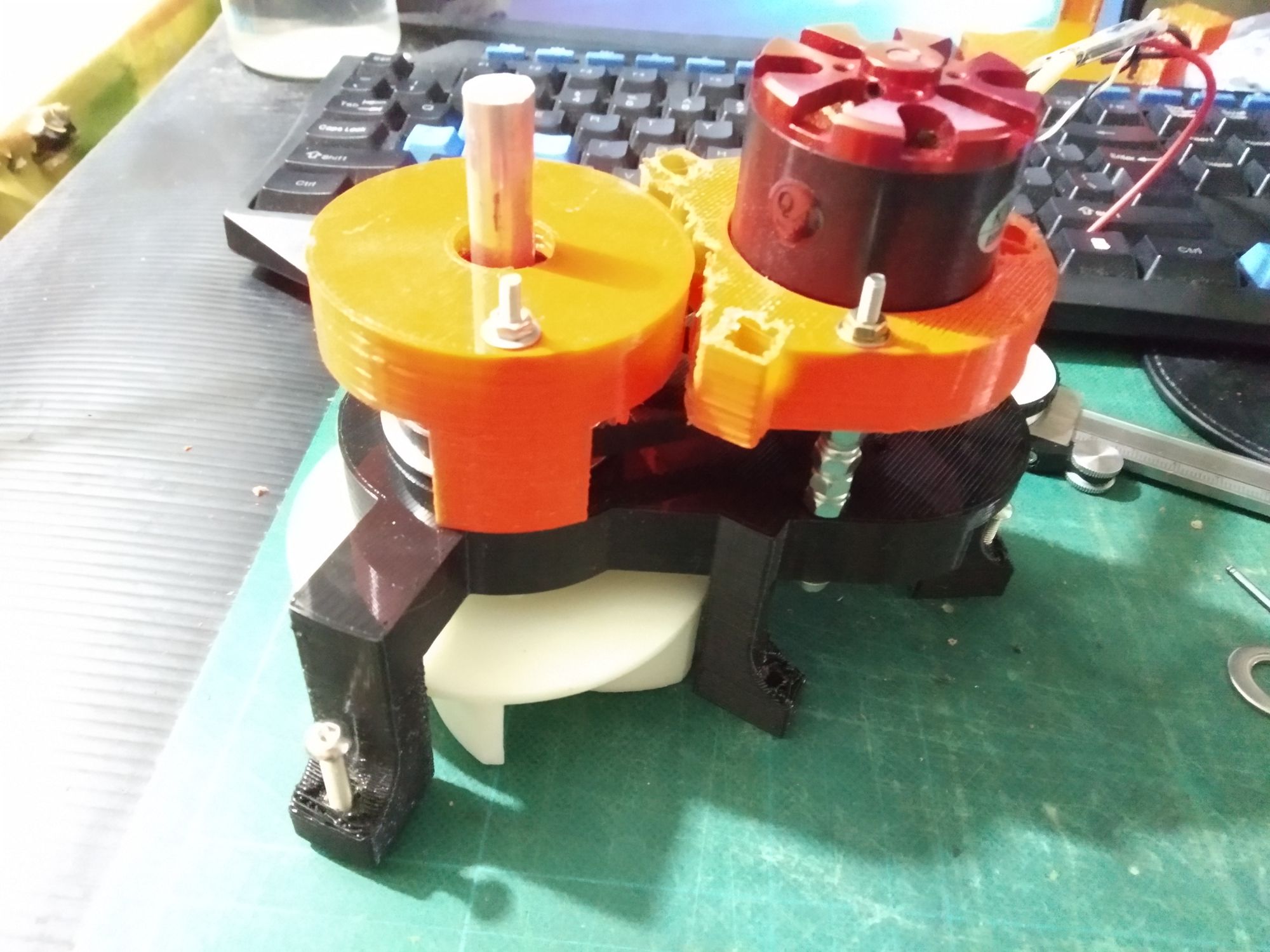
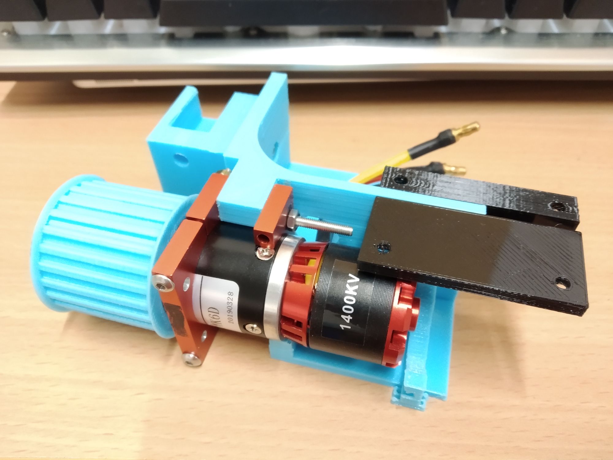
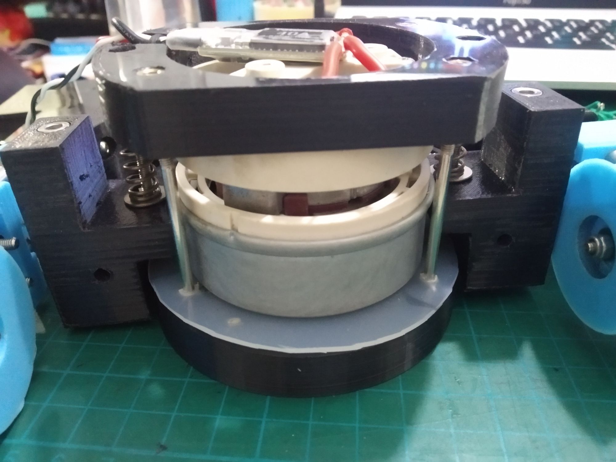
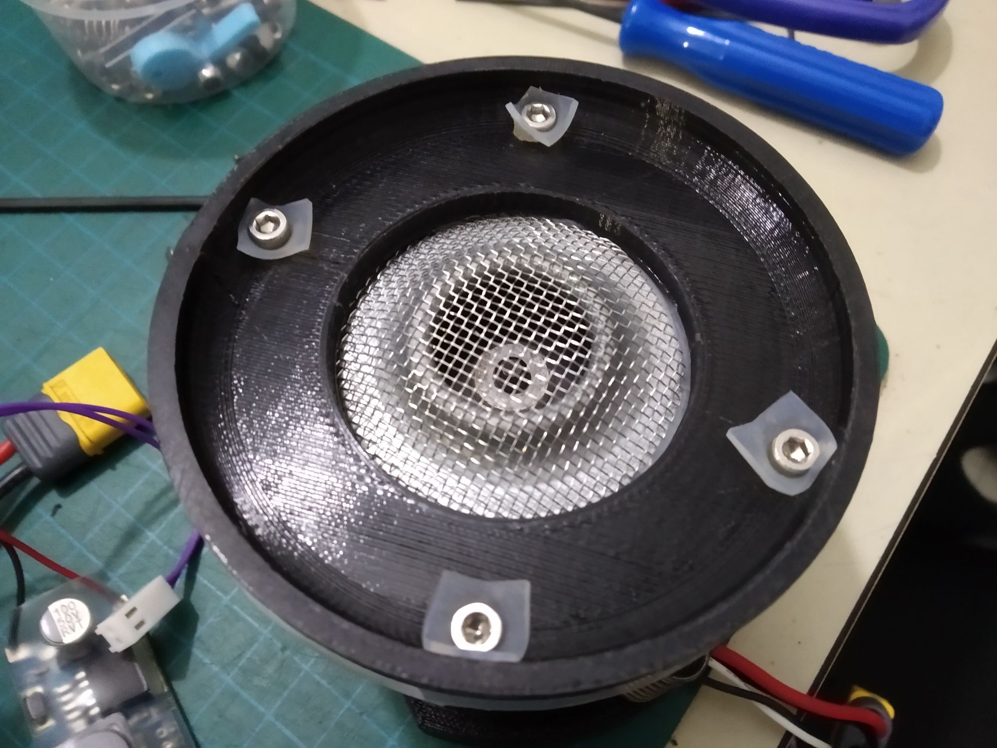
Vacuum
Since the play-field was not magnetic, using magnets to increase downforce on the field was not an option. A brushless vacuum cleaner was used to provide suction against the floor.
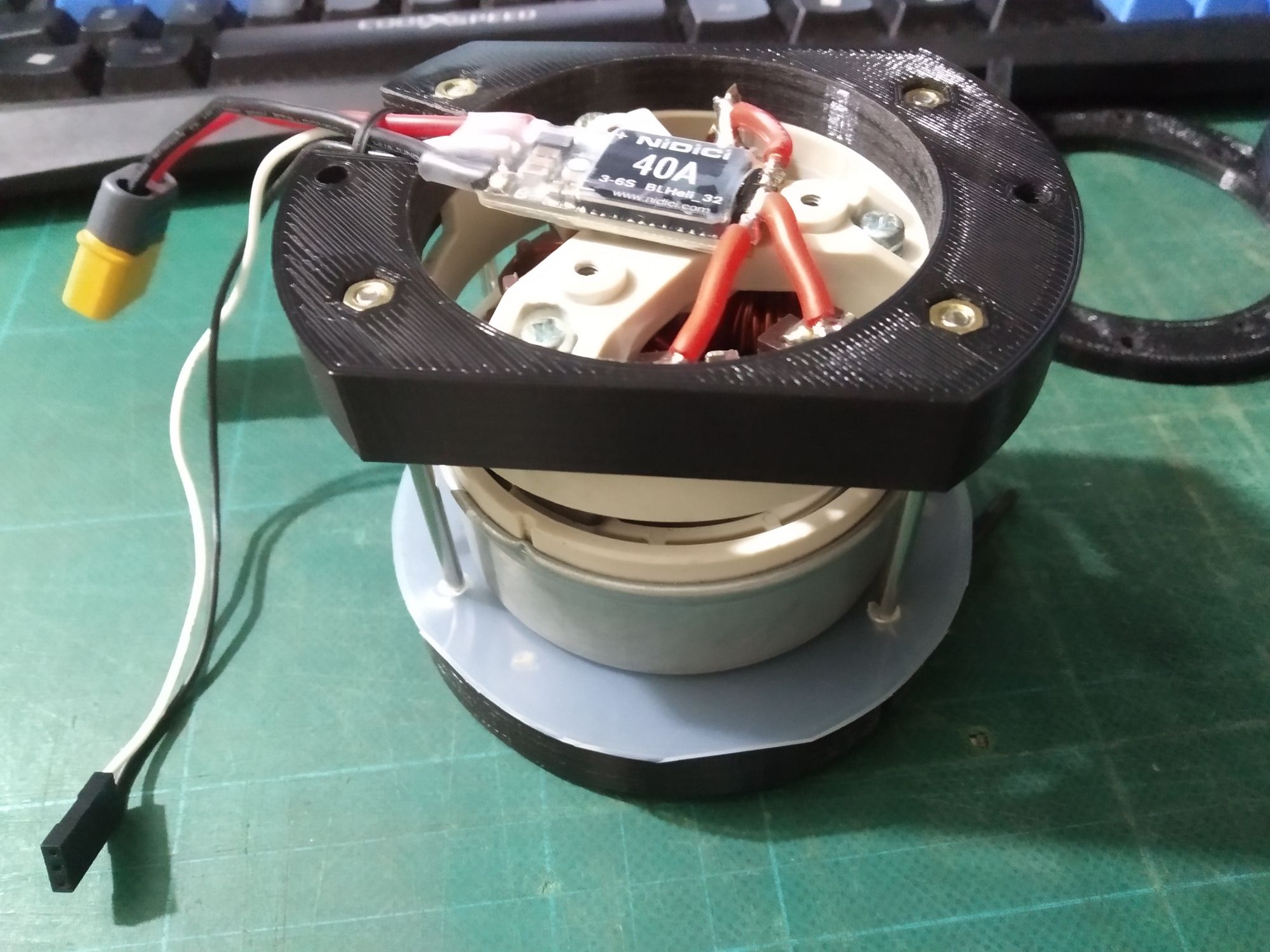
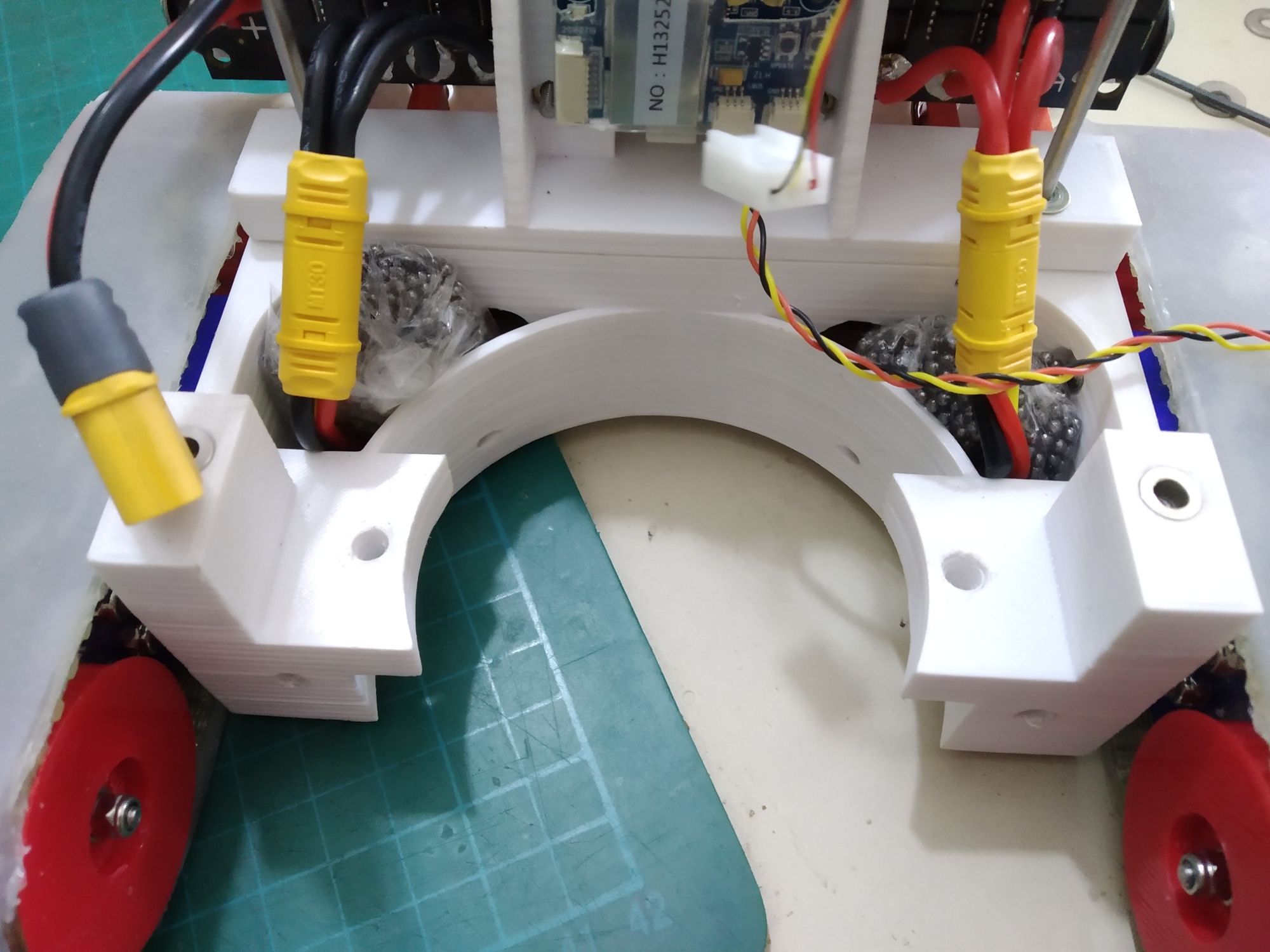
I realised from testing that the vacuum must form a good seal with the floor to provide the most suction. As such, the vacuum was mounted on springs to ensure that the bottom of the vacuum always formed a good seal with the floor.

The spring mount for the vacuum. This also allowed me to adjust the spring tension by adding/removing washers.
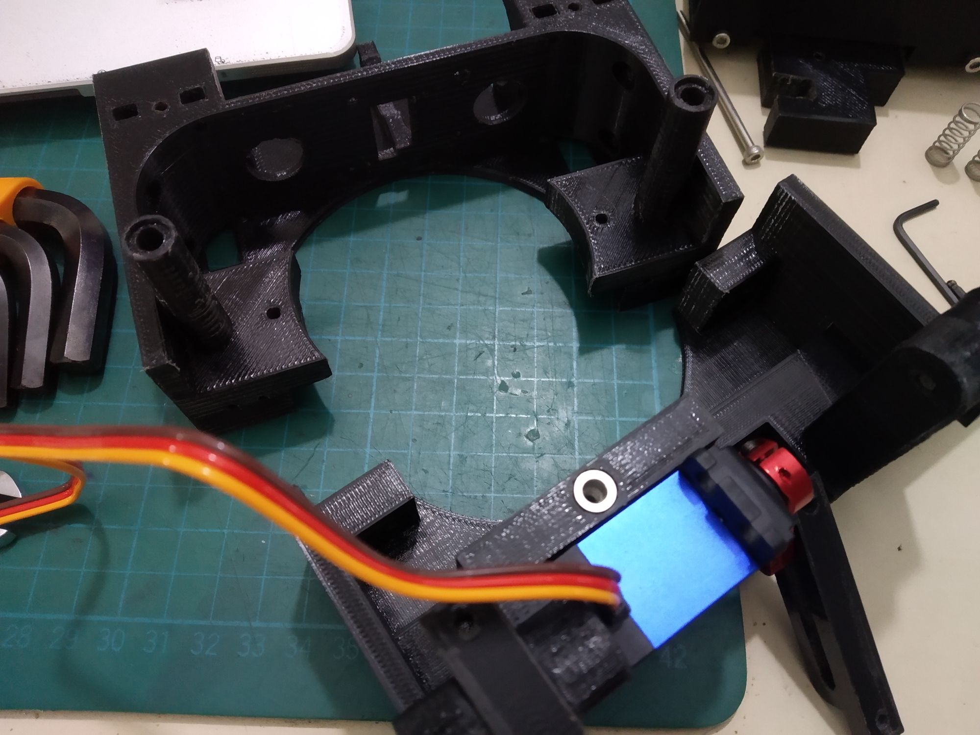
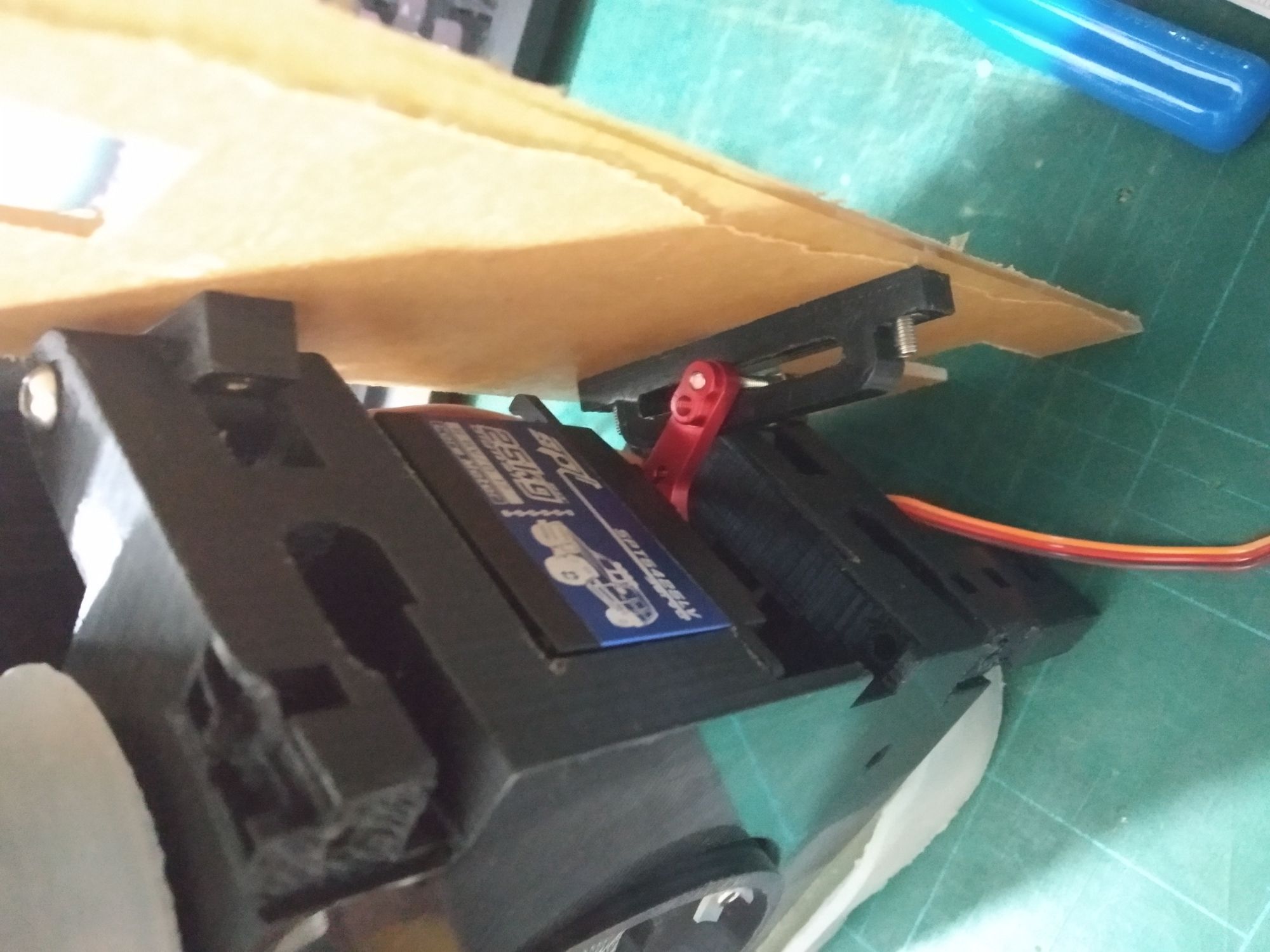
Front
Not much left other than to mount the front scoop. A servo was mounted inside to lift the scoop.
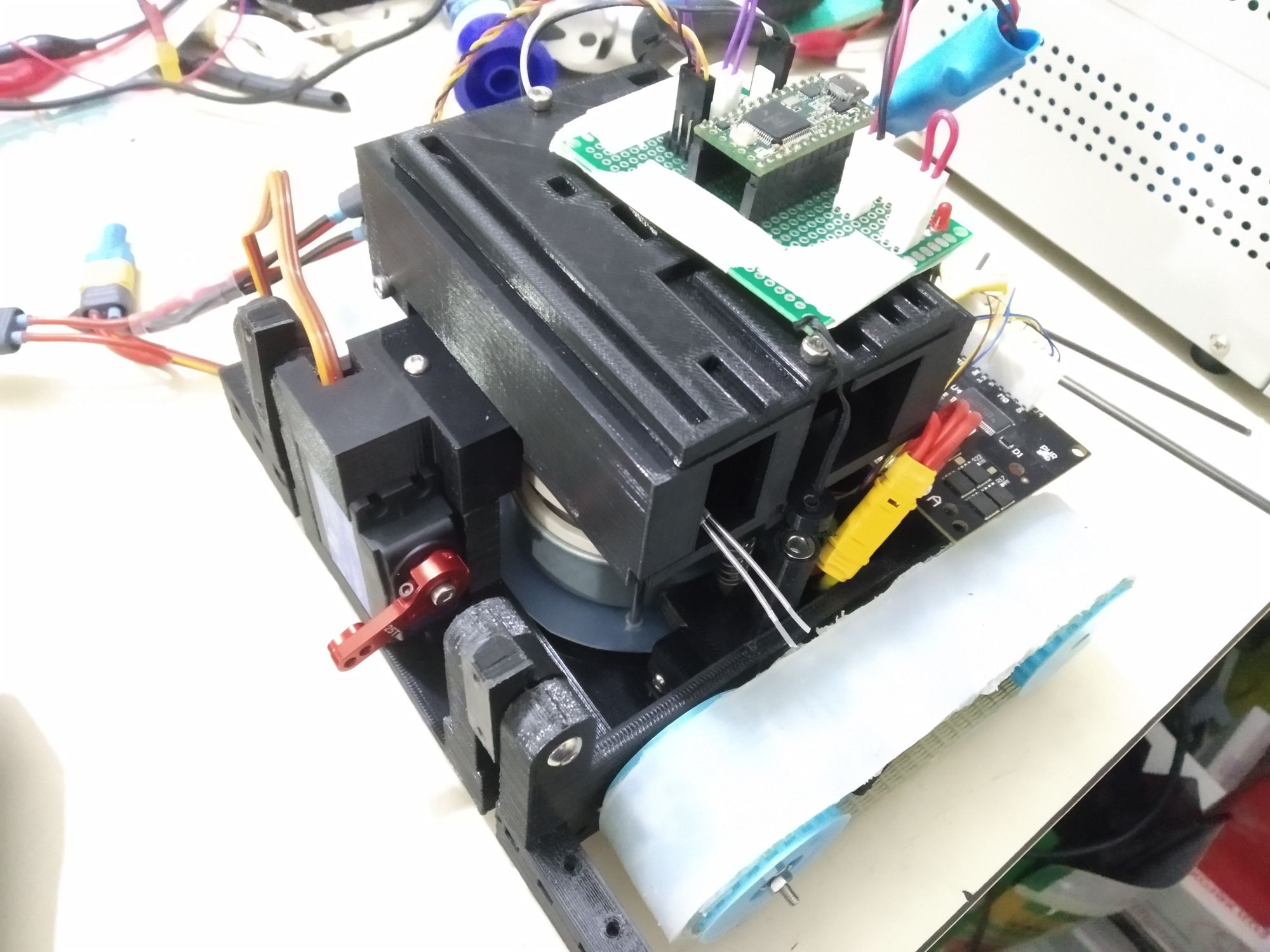
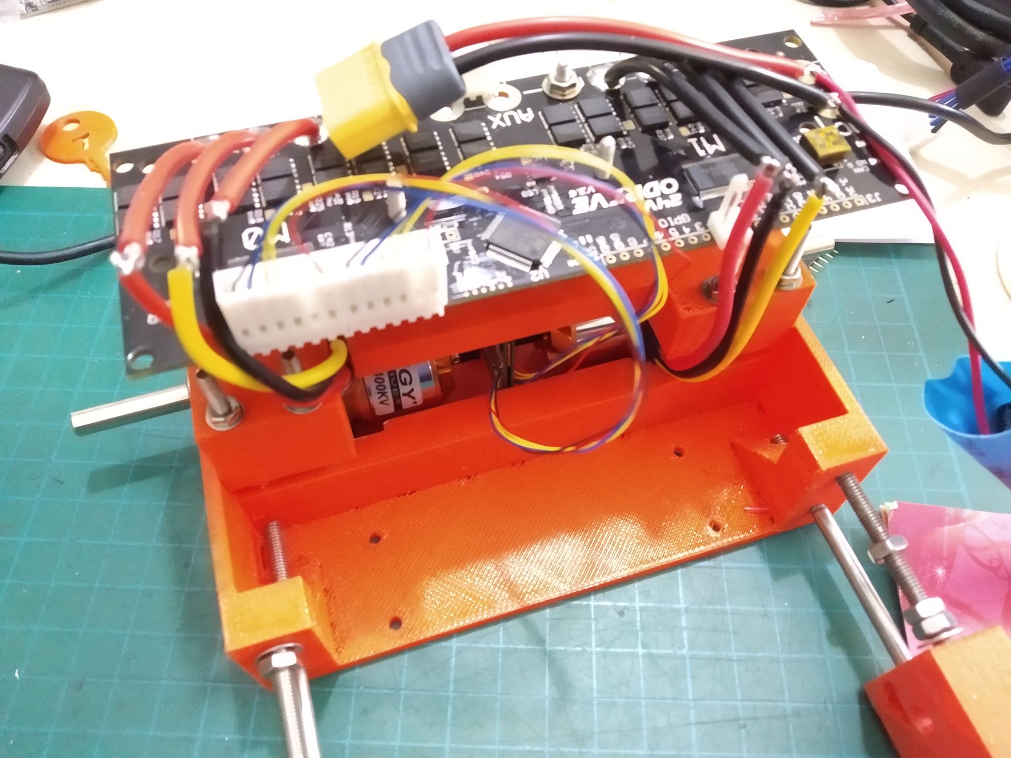
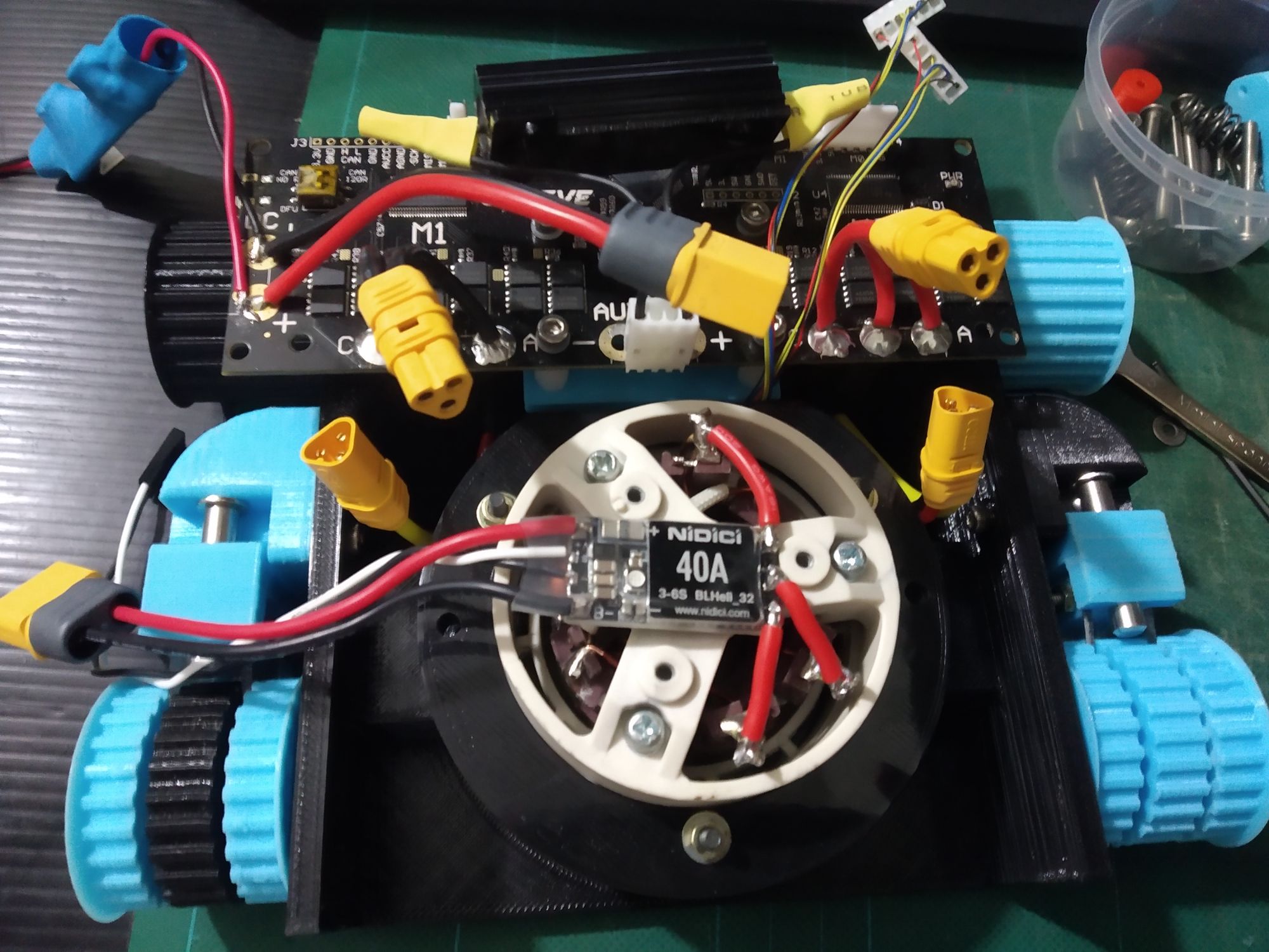
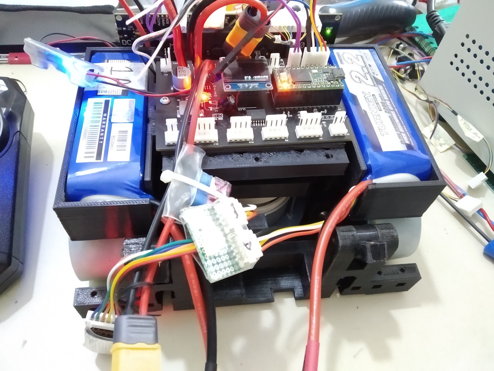
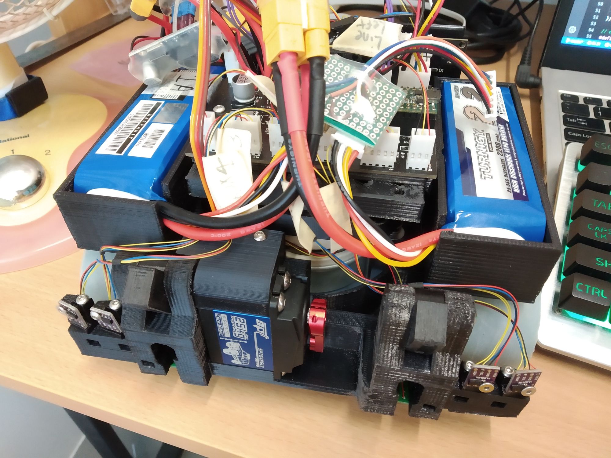
I experimented briefly with mounting the batteries and controller by stacking them on top of each other. Not too happy with how high the whole stack was, so I shifted the batteries to over the tracks.
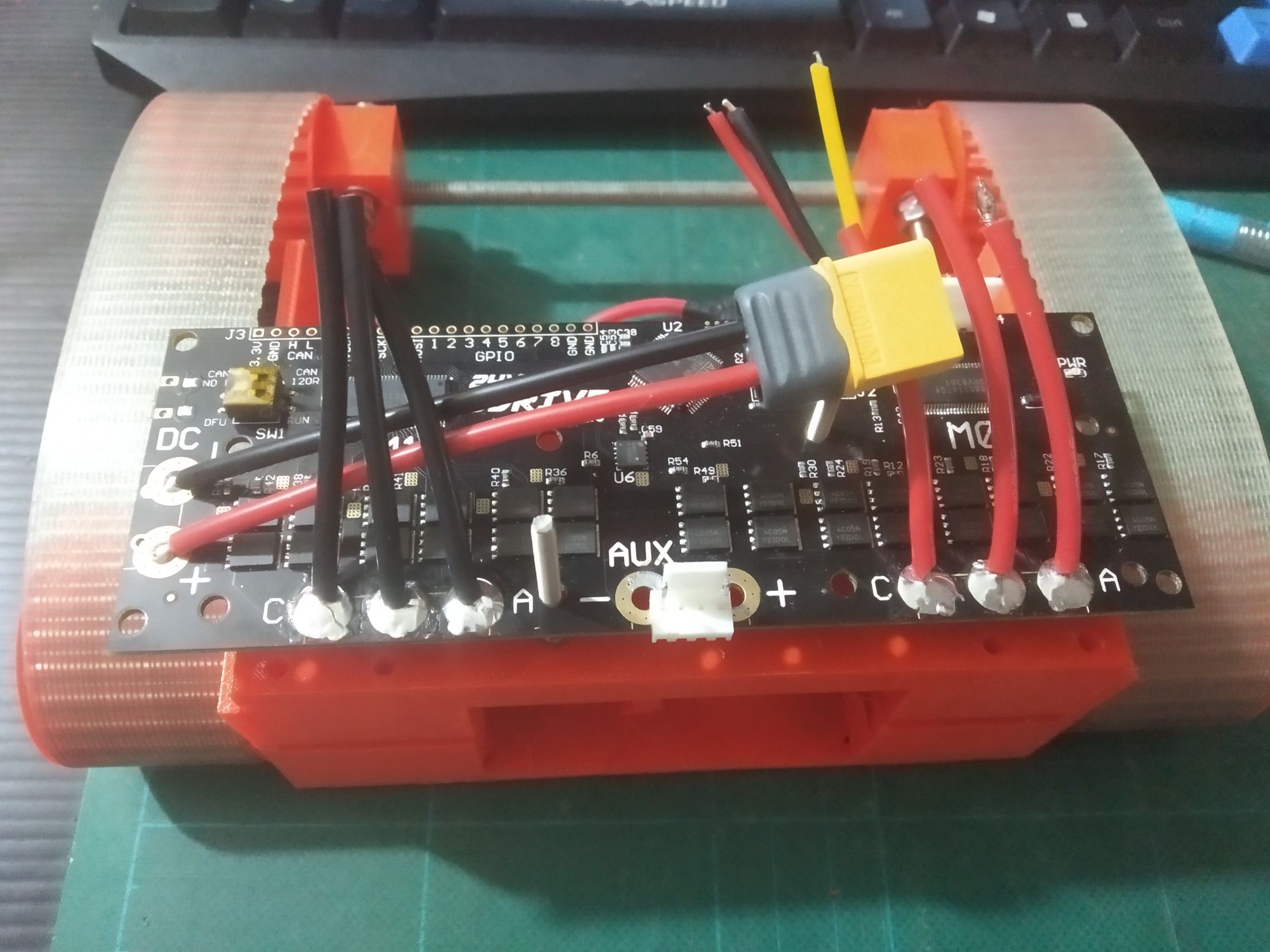
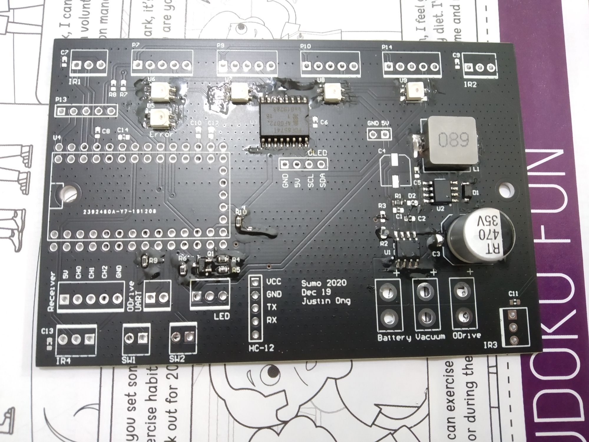
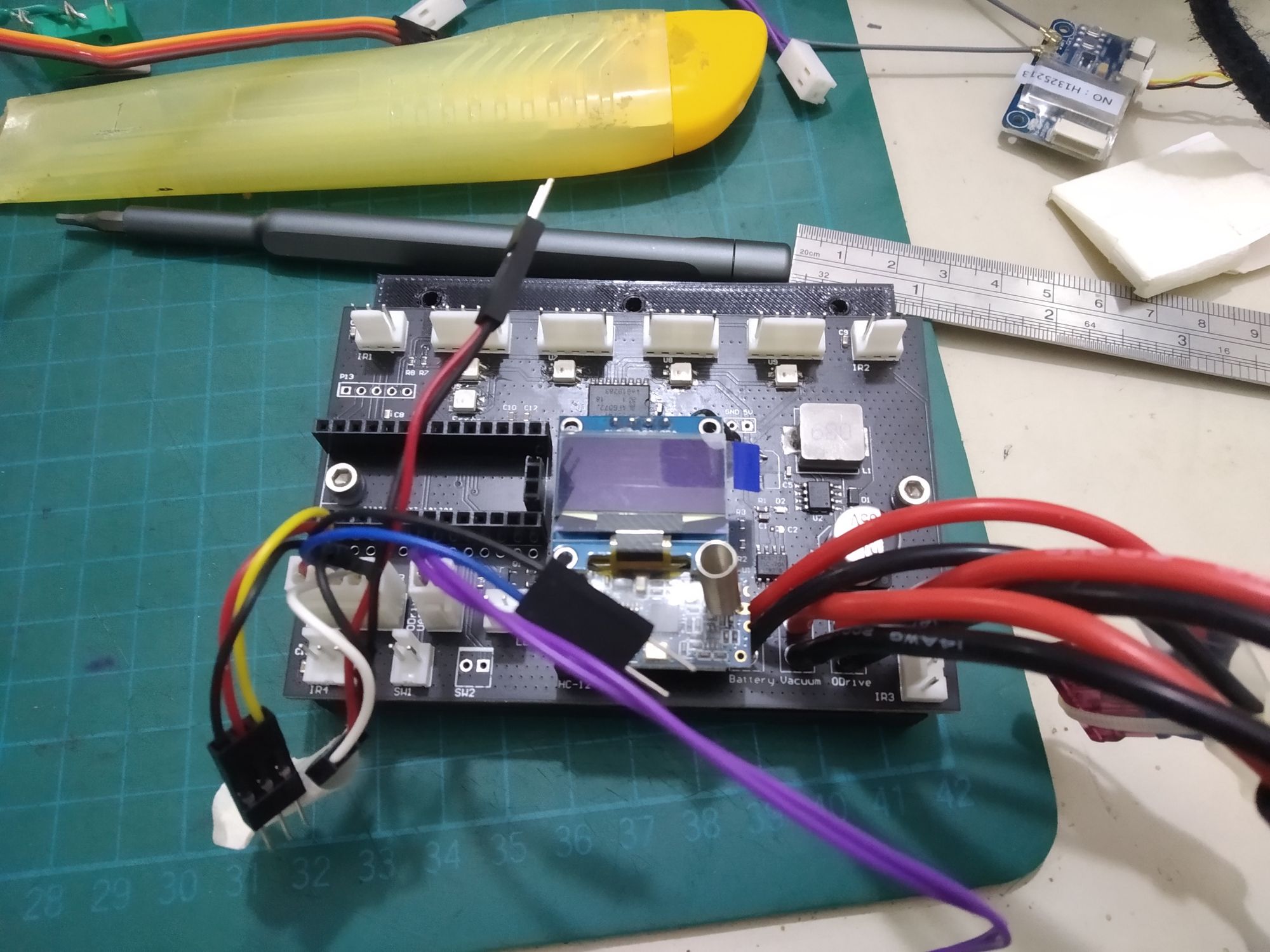
Electronics
The robot was controlled with a Teensy 3.2. A PCB was made to simplify connections.
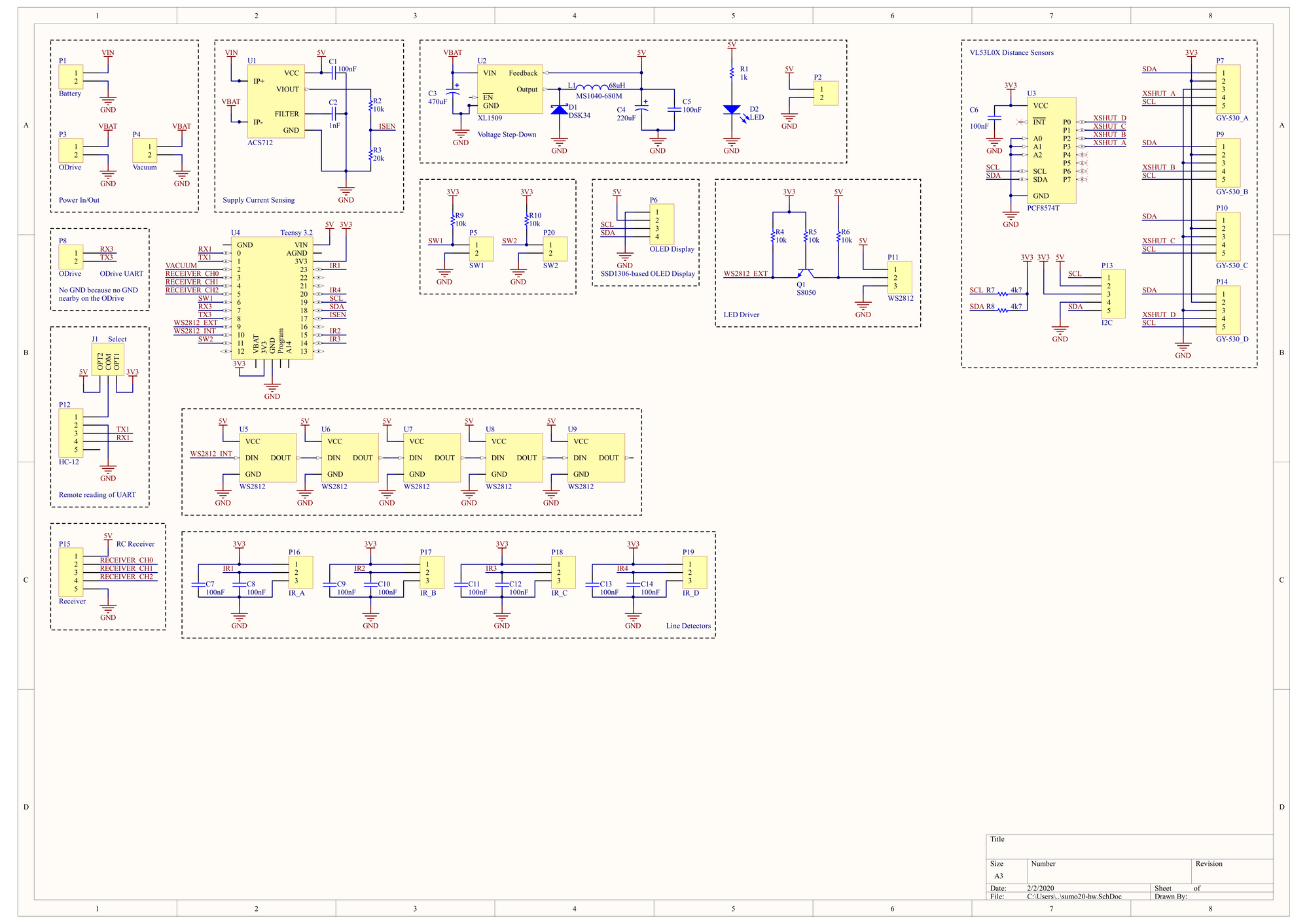
A few footprints for random modules were added just in case:
- HC12: UART-based 433MHz transceiver, useful for remote viewing of uart debug logs
- SSD1306-based OLED display: this was added primarily to display current drawn, though it was very useful in the end for displaying the state of sensors as well. This was much much more useful than intended.
- External connector to drive WS2812 LEDs.
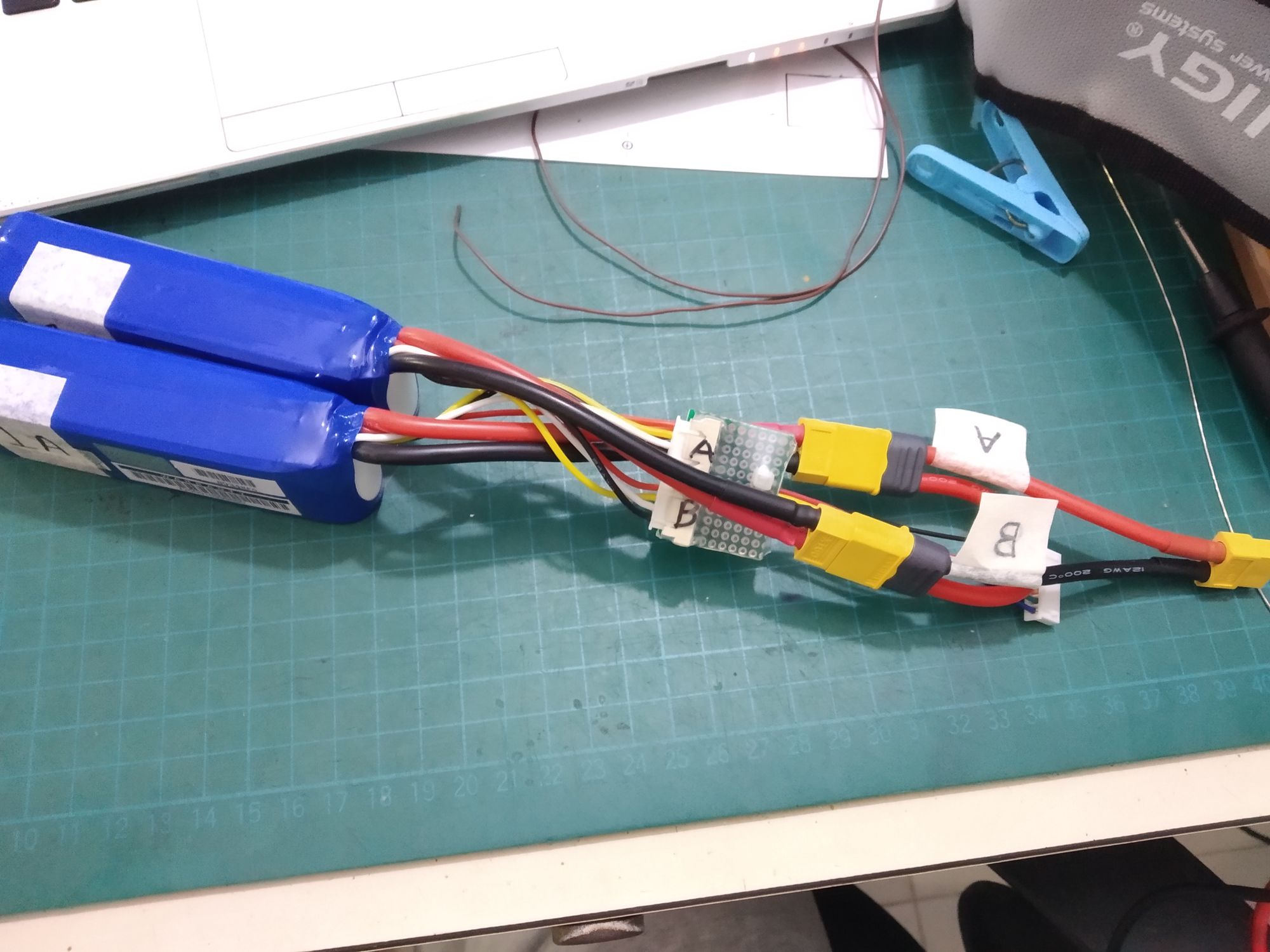
The robot was powered by two 2.2Ah 3S in series for a few reasons:
- 6S is the upper limit of the 24V ODrive I'm using
- Its far cheaper to buy two of these and series them myself as compared to buying a 6S battery of similar capacity
- I'm more likely to be able to make use of 3S packs rather than 6S packs in other applications
Sensors
Four VL53L0x were mounted in front with holes cut in the scoop so that the scoop did not obstruct the viewing angles of the sensors. My objective was to mount the sensors as low as possible, but this proved to be a terrible idea later on because the sensors still saw interference from the edges of the scoop sometimes.
Four QRE1113GR were also mounted in the corners of the robot to detect the white line around the ring.
Software
Software was written using the Arduino framework. Nothing much to say here, just standard control stuff.
Remote control was achieved by reading the data from a Flysky X6B receiver over IBus (UART-based protocol).
The Teensy 3.2 then controlled the ODrive over UART. A bit of patching had to be done to the ODrive's firmware:
- The ASCII protocol did not support incremental movement. Solved by adding the
itcommand - When the ODrive switches from velocity control (used in RC) to position control (used in autonomous control), the stored position for position control is not updated. This results in the motor spinning moving more than expected. With assistance from the community, the firmware was patched specifically for my situation.
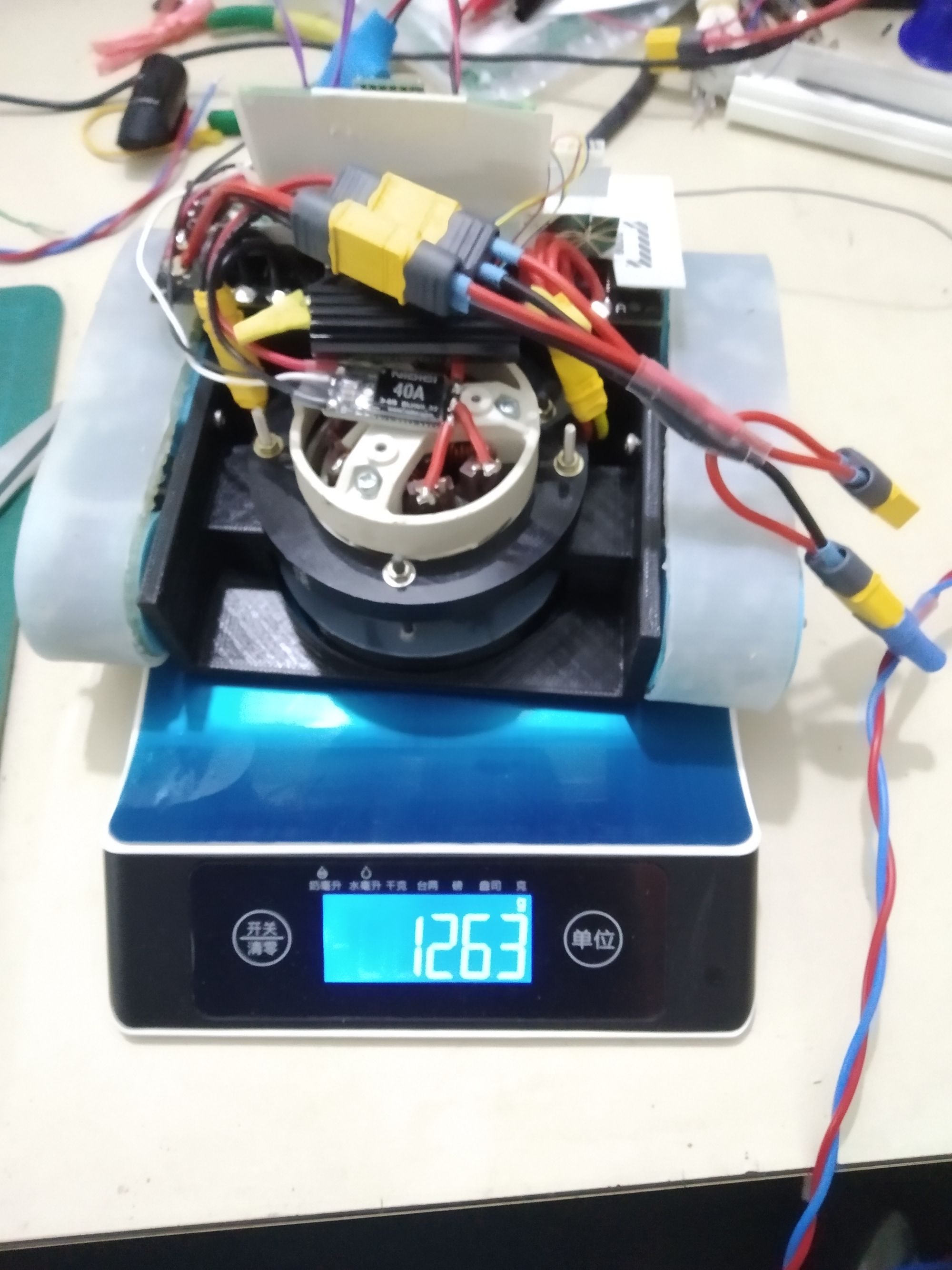
Gaining Weight
Competition Performance
So that went horribly. Immediately upon starting round 1, something went wrong, resulting in that familiar smell of burnt electronics.
The robot was meant to do this:
It appeared at the time that the right axis failed to respond (or likely went into an error state) while my routine was waiting for the axis to move a preset amount.
I later learnt (or rather, had the right motor vent it's magic smoke) that the right encoder and/or the motor had failed. Not knowing what happened, I could only proceed to round 2 (after vigorously sniffing to see if I could determine where the smell came from).
I suspect that in round 2, the ODrive was in an error state, not moving at all.
Other than having to replace the right motor with a spare, there was no other damaged components.
I can sum up the RC rounds in a single sentence: I'm terrible at actually controlling robots.
Post Mortem
- I need more practice: both in terms of how to handle the robot (and perhaps put exponential control on the turn channel) and autonomous strategies
- Putting some form of non volatile memory on the robot to log events would be very useful - I have no way of reconstructing the actual state of the ODrive.
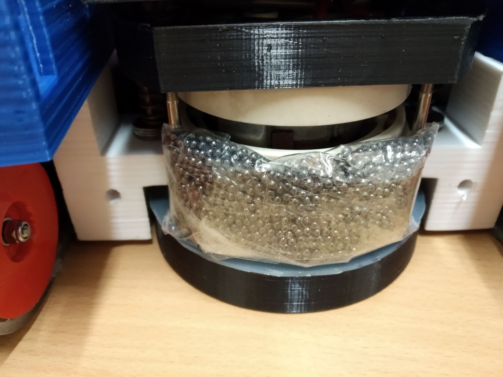
- Needing to add lead shot to weigh the robot down to meet the 3kg requirement was sloppy - I had to add nearly 700g, which could have been used to add a bigger vacuum motor.
- Communicating between two microcontrollers (one Teensy 3.2 as the main controller, one STM32 on the ODrive controlling the motors) was not ideal, I had to extend the ASCII protocol of the ODrive to make some functionality possible. Having to write complex code to poll the state of the ODrive was also irritating to write and debug. A compromise would be to communicate over the native protocol.
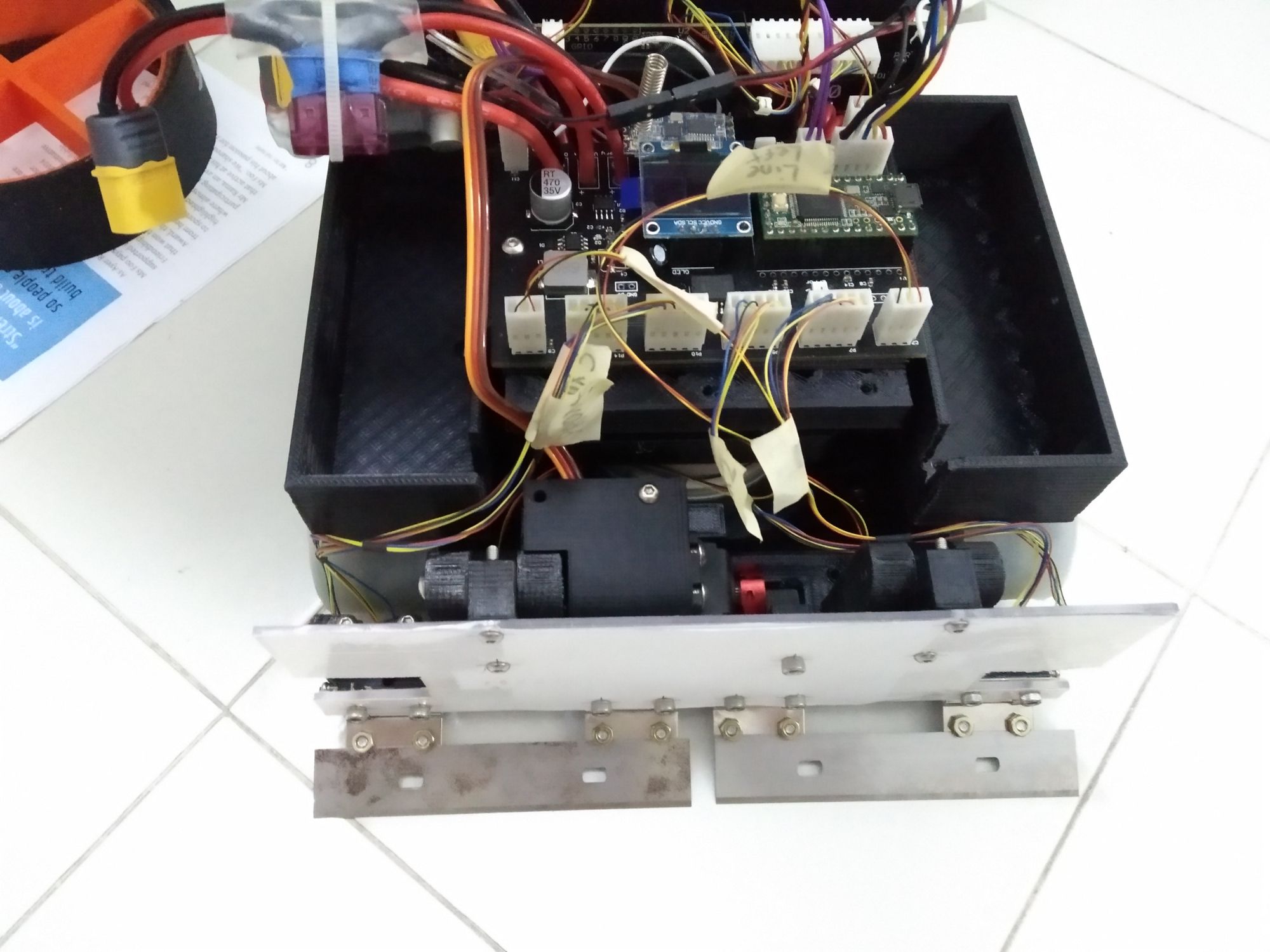
- Tracks may not be the "obvious best": From the first autonomous round, it would appear that a robot with commercially available wheels was still able to push my custom tracks and my vacuum.
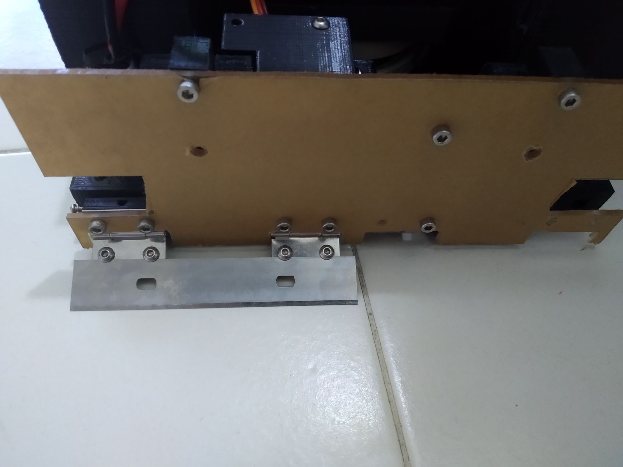
- Using sharp blades as my scoop to scrape the floor was great conceptually, but horrible in practice because the floor was not rigid, resulting in the blades digging into the floor. Additionally, the surfaces of the play field was quite terrible - there were protrusions/gouges, and had I left my blades sharp I would have gotten caught on them.
Conclusion
I've actually had a lot of fun optimising and adjusting the robot over the lead up to the competition. Regardless of the terrible failure at the actual competition, this project has improved my CAD skills a lot and showed me that brushless motors are usable in robotics.