(W)AVE 2.0 - Haptic Cloth
What if we could touch light? Tactility of Light and (W)AVE began to explore this idea by using light-reactive haptics to explore a space. From a technical perspective, the method of implementation limited the density of the haptics. Naturally, we asked (and attempted to answer) "how can we take this to the next level?"
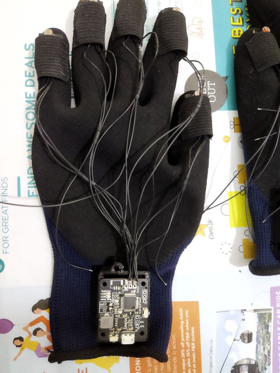
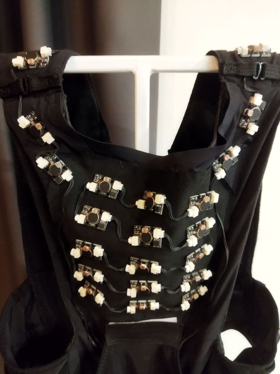
This post briefly documents the development of a set of Haptic Vests and Haptic Gloves to allow one to touch and feel light. These gloves and vests are used as part of (W)AVE 2.0, an experiential installation running until 22 January 2022. For more information, check out @tactility_of_light.
Design Considerations
The prior implementation relied on an Arduino and its 6 (up to 8) analog-to-digital channels to control a corresponding number of vibration motors.
However, we realised that attempting to scale that directly has its own issues:
- Since the vibration motors had to be separated from the controller (to allow for flexing of the material), we would have to design some sort of microcontroller board and haptic "module", then connect both with wires, then copy and paste this across the vest/glove.
- More critically, we needed a way to adjust parameters (eg sensitivity and maximum vibration strength) easily, ideally without having to flash new firmware.
These considerations steered us towards developing independent haptic modules with on-board logic for mapping received light to vibration motor strength. Yes, this could be done with a couple of analog components, with configuration done by passing a few analog levels to the modules to "configure" their behavior. Of course, we took the easy way out and chucked a microcontroller onto every board.
Microcontrollers
Given the current pandemic-induced component shortage, sourcing a few hundred of the usual ATtiny's would be a little pricy and problematic. Having seen the three cent microcontrollers discussed (and wanting to play with new toys), we settled on the PFS172, which checked all the boxes:
- Multiple-time programmable
- Couple of ADC channels (of which we only need one)
- Couple of timers with PWM output support (of which we only need one)
Another key reason behind the using the PFS172 is the support from the Free PDK suite of tools - this meant we could use standardised tools (like SDCC) instead of a vendor-specific IDE and stripped down C language.
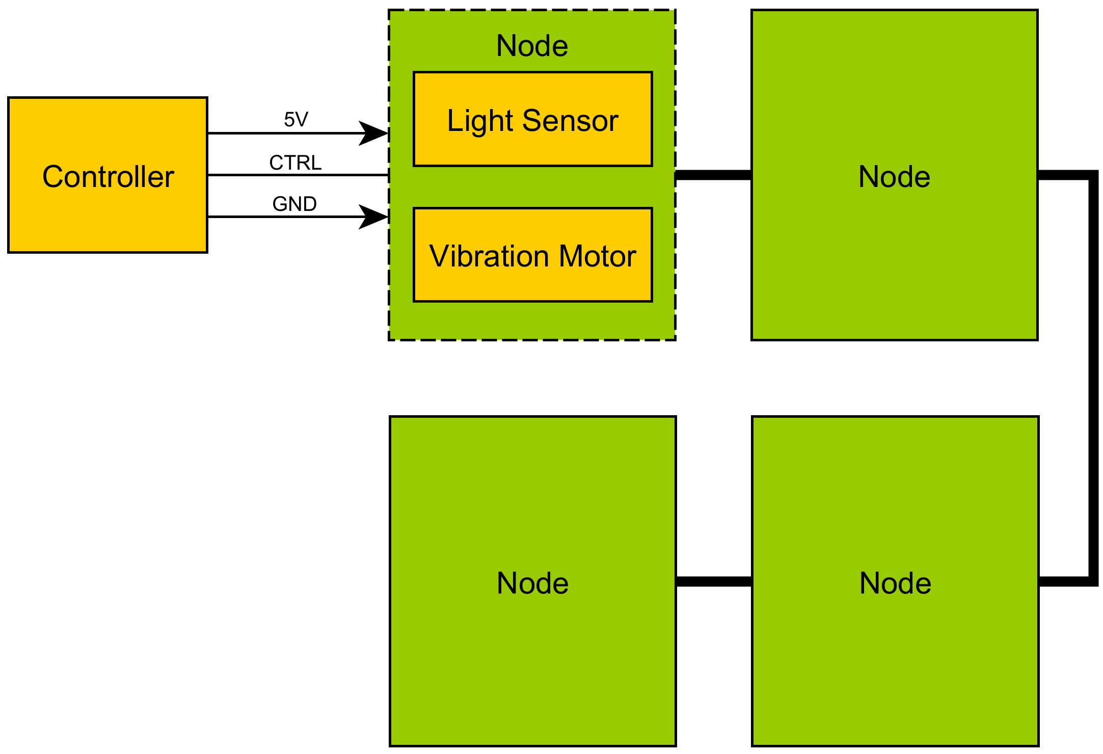
Architecture
For adjustment of parameters, a transmit-only 1200 baud UART line was connected to all the modules. This allows us to daisy-chain the modules since all three lines (power, control and ground) can be directly shared between modules.
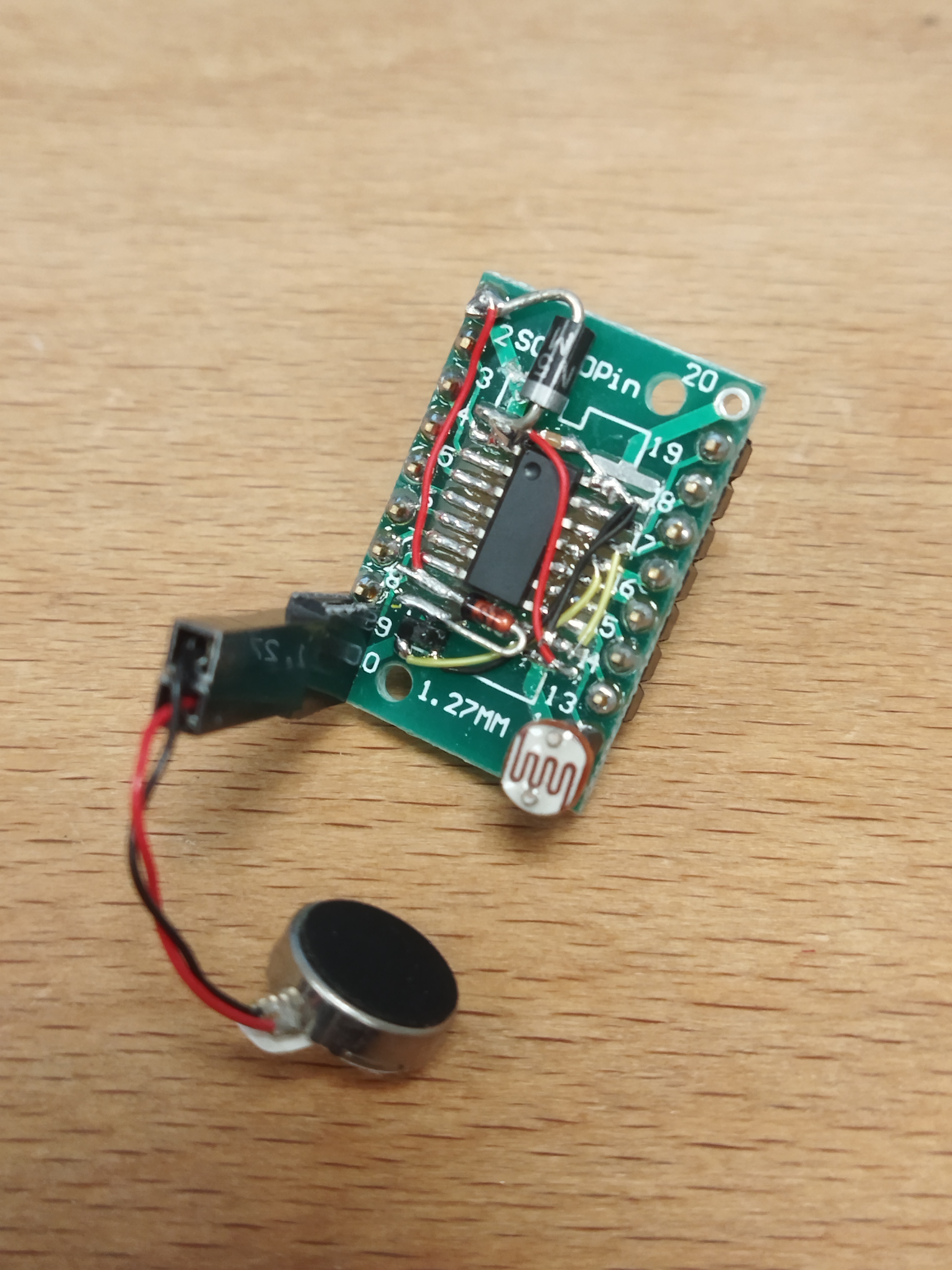
Nodes
The nodes themselves were relatively straightforward, reading an ADC channel and mapping it to the duty cycle of a timer. A simple UART receiver was implemented in software since the PFS172 has no hardware UART peripheral.
Figuring out how to handle firmware flashing was a little tricky: the original plan called for using the PFS172-U06, where all 4 GPIO pins were also used for programming. When PA3 (also used to control the vibration motor because it is the only PWM-capable pin) is pulsed for flashing, the vibration motor activating causes flashing to fail. D2 in the schematic below prevents the motor from being powered when flashing.
As luck would have it, we could only source the PFS172-SO8, which also has another PWM-capable pin PB7. This eliminates the prior issue, but the diode was left in to hopefully prevent issues with flashing due too much capacitance on the VCC line when multiple modules are chained together.
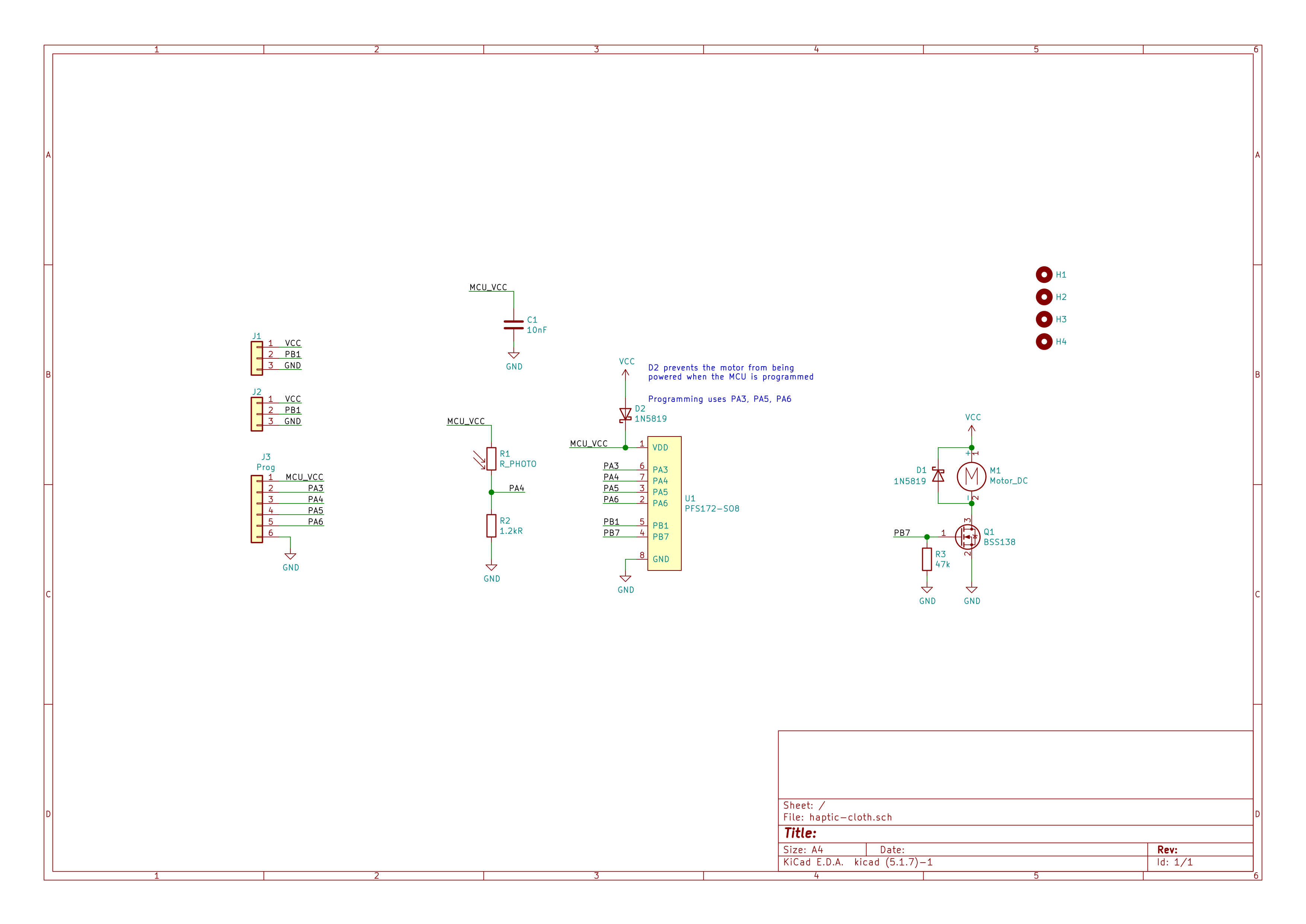
The PCB project can be found here, while the firmware running on the PFS172 can be found here.
Controller
Power
The obvious choice for powering the nodes is to use some form of Lithium-Polymer battery due to the wide range of form factors and energy density. Conveniently, using a power bank controller like the IP5306 provides battery charging, low voltage cutoff and a regulated 5V output in a single package.
We used the I2C-enabled variant of the IP5306 for two reasons:
- We can limit the charge current, which defaults to 2.1A. This is too high for the 800mAh batteries we use for the gloves.
- The discussion here indicates that the low power cutoff feature can be disabled by setting bit 1 of
SYS_CTL0. Unfortunately, as mentioned in the same thread (which we didn't realise before fabricating the boards), when this is enabled, double pressing the power button no longer turns off 5V output.
As such, to "disable" the low power cutoff feature, we retrofitted four 330ohm resistors to three GPIO pins of the microcontroller, then pulsed them just long enough to trick the controller into thinking there was a load.
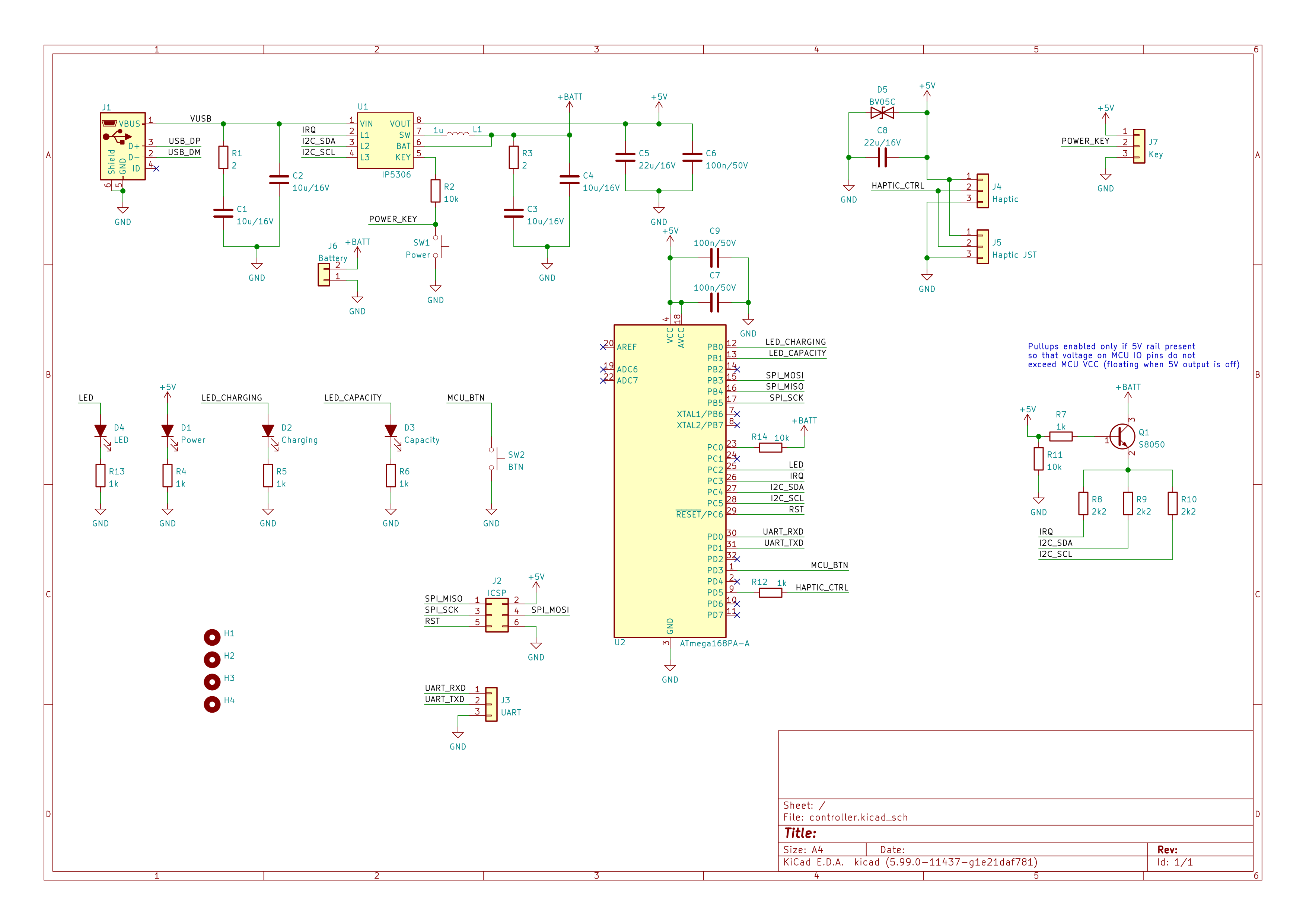
There were also a couple of mistakes made in the schematics below: L1 and IRQ of the IP5306 have their pins swapped.
Configuration
As the PFS172 themselves have no runtime-modifiable non-volatile memory, an ATmega168P is used on each controller board to store configuration information in EEPROM, and to configure the IP5306. The firmware running on the ATmega168P can be found here.
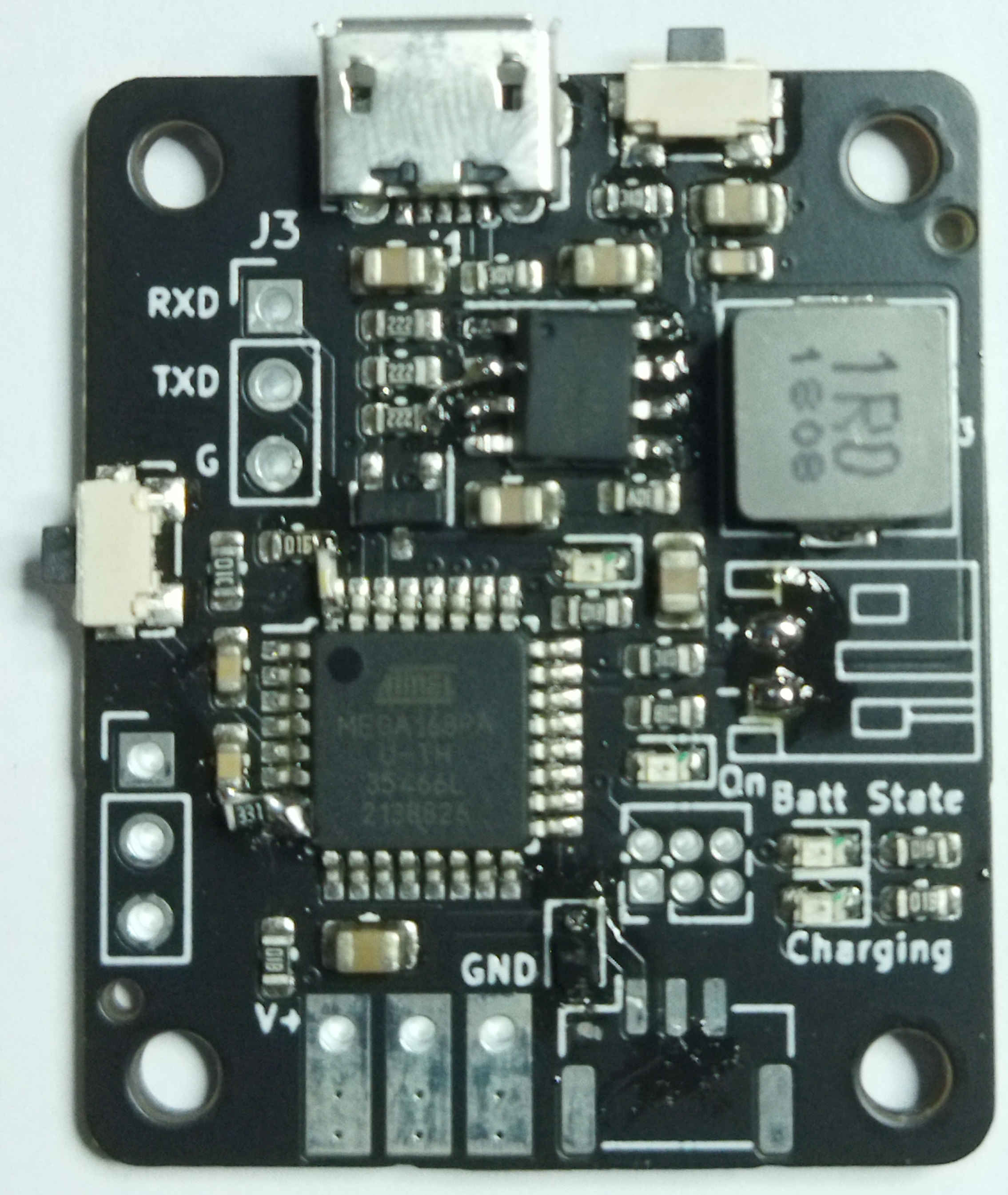
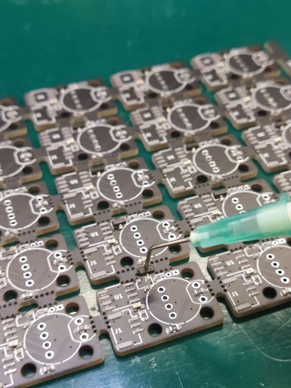
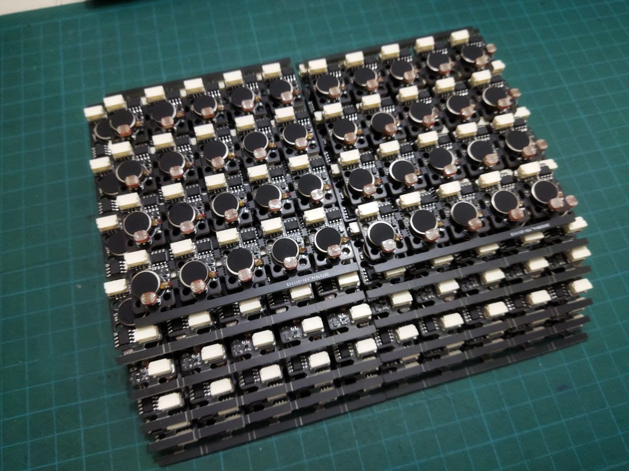
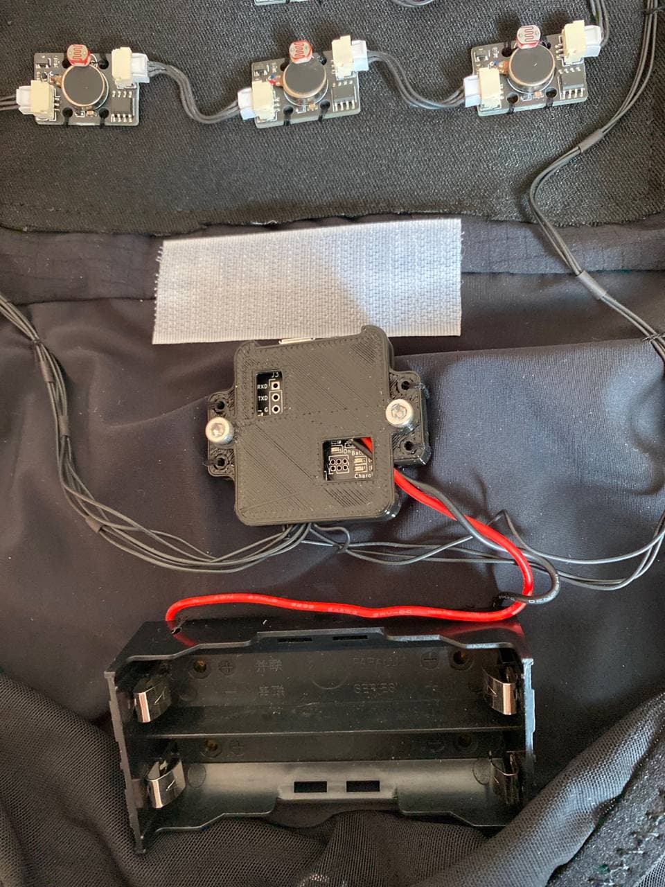
Final Assembly
The panelised node boards were hand populated (and was a terrible idea) and reflowed on a hot plate.