Singapore Robotic Games 2019
On a whim, I decided to participate in the Sumo categories in SRG 2019. This post aims to document and explain the design decisions for my robot, which had to fit within 20cm x 20cm and weigh less than 3kg. Most parts were bought from Taobao.
You can find the PCB and source code here. The models for the 3D printed parts have not been uploaded because they were completely customized and I believe would be useless anywhere else.
I built this with a few goals in mind:
- Low Cost
- Simple, buildable with the equipment I had access to
- Of course, to win.
Not surprisingly I didn't get anywhere close to the top. The biggest issue I had was the lack of traction, resulting in my robot simply skidding without gripping the floor.
Drive System
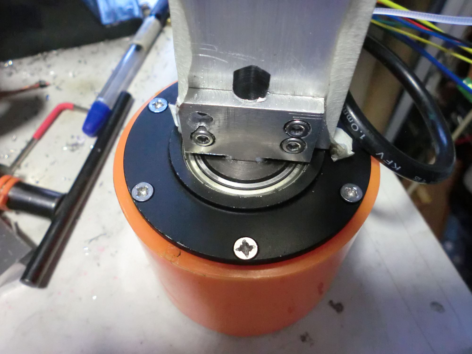
So first, my drive system. I decided to use two electric skateboard wheels. These are skateboard wheels with a brushless motor integrated directly into the wheel. The direct drive of these hub motors simplifies the mechanical portion - rather than having to gear down high RPM motors, I just needed a way to mount the motors securely.
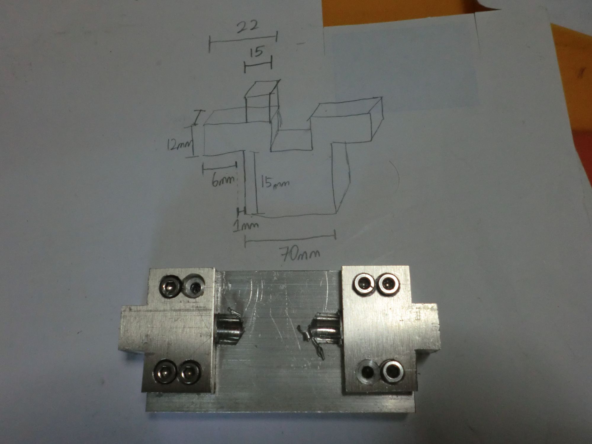
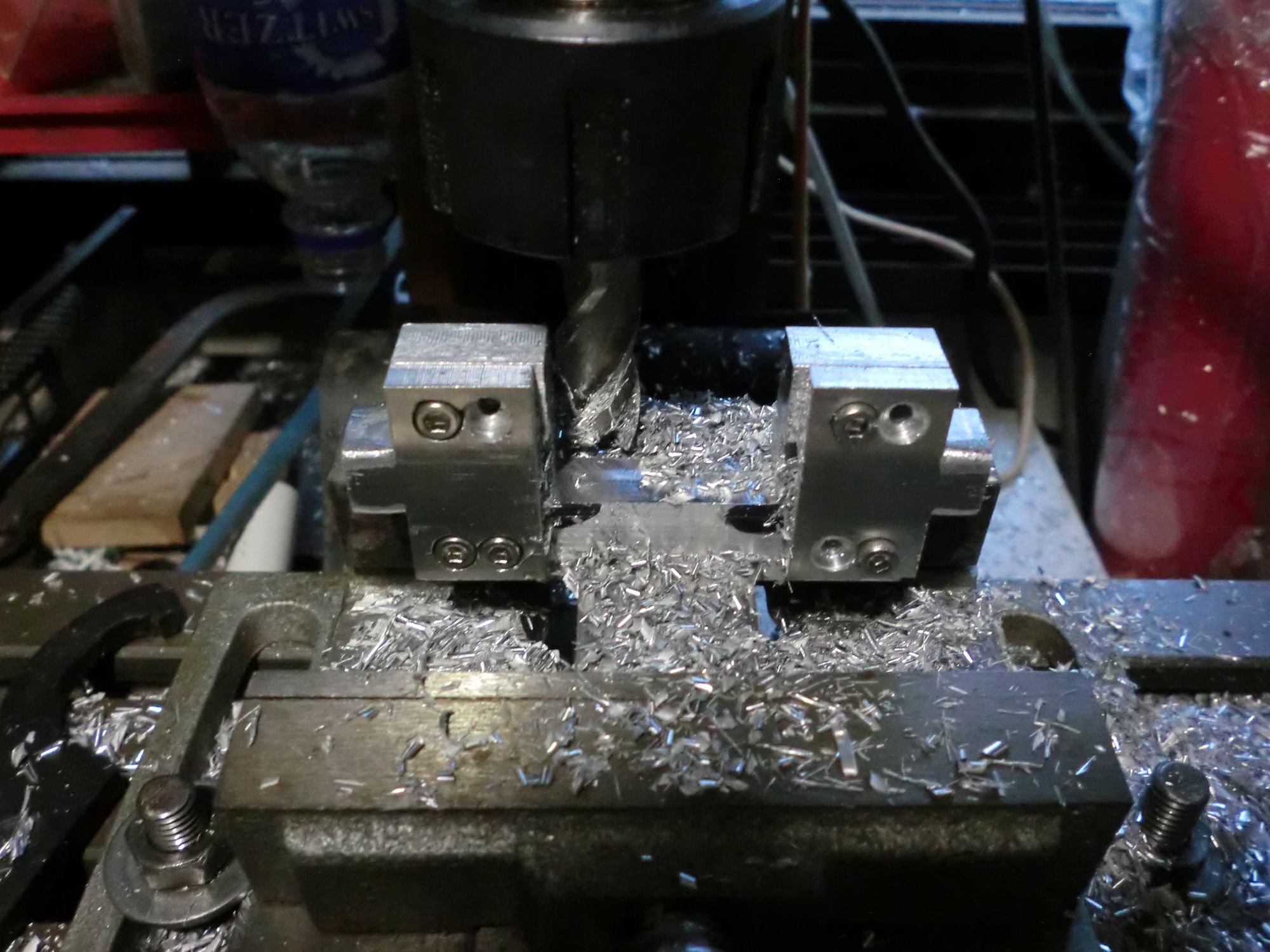
The wheels I got were meant to be mounted to a 12mm square shaft with a bolt through the middle, usually to a metal piece specifically made for skateboards. Rather than 3D printing this piece (which would likely have failed horribly given I could only print PLA), I decided to try and machine a similar piece out of aluminium plate.
Since I only had 10mm and 5mm plates, I stacked (then screwed) then together to form a 15mm thick "plate" so that I could fill out the entire 12mm x 12mm square mounting hole in the wheel.
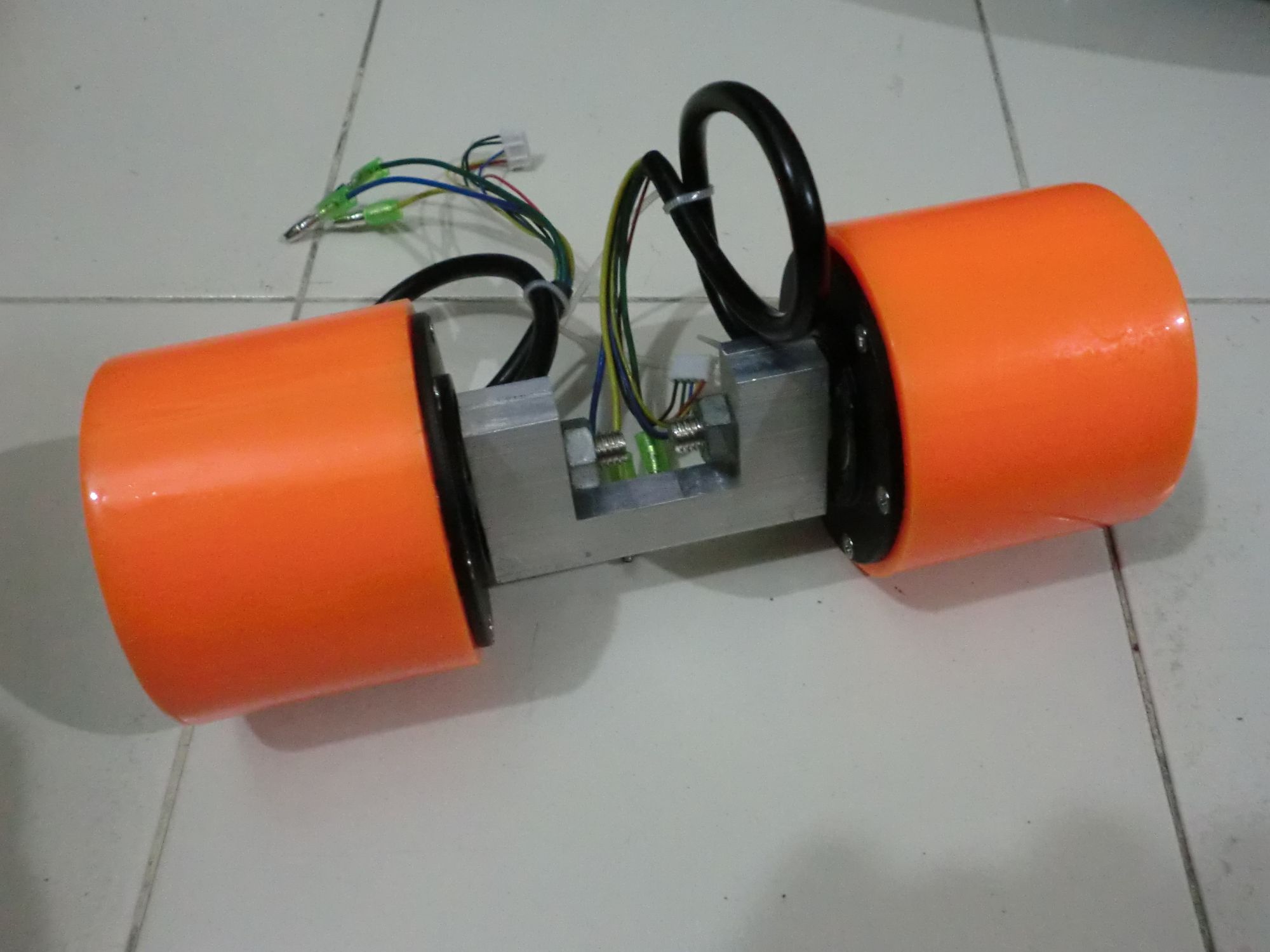
One huge issue with using these wheels: they're severely overkill for this purpose. The specifications (even if you derate them by 50%) state that one motor has a max load of 100kg. These are 300W~ motors. This would normally not matter, except that the wheels are around 800g each, a huge part of the weight budget. That assembled wheel structure above weighs nearly 2kg.
Tires
The smooth, hard tires on the wheels did not fit my purpose either. I wanted them far softer to provide more traction. I don't know why I didn't just order proper casting silicone, but I decided to try casting silicone caulk to make softer tires.
After reading this Instructables, I decided to try the same thing. I printed moulds that fit around the wheel hubs, then tried to fill them with the silicone mixed with corn starch. This went about as well as you'ld expect - after mixing the corn starch in, the whole mixture had the consistency of thick gel. Stuffing that into a mould with 5mm~ of clearance was messy and left a lot of voids.
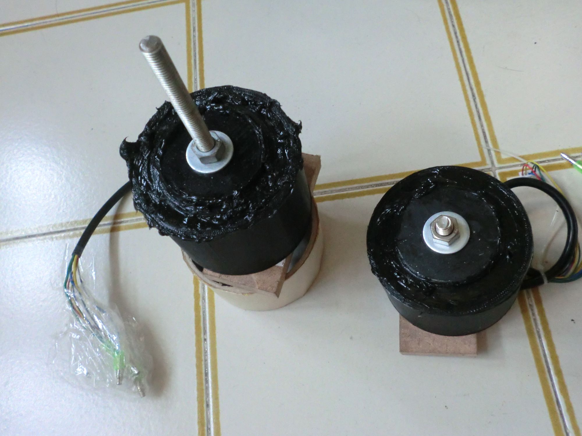
The left wheel was my first attempt - this was the result of me trying to stuff in thick gel with first a plastic bag like cake frosting, then later with a spoon after that did not work out at all.
The right wheel looks slightly better, because I squeezed the silicone (without mixing in corn starch) through a straw into the mold directly.
In hindsight, applying some sort of release agent would have been a great idea. The tire was not going to slide off the hub motor, let alone separate from the mould.
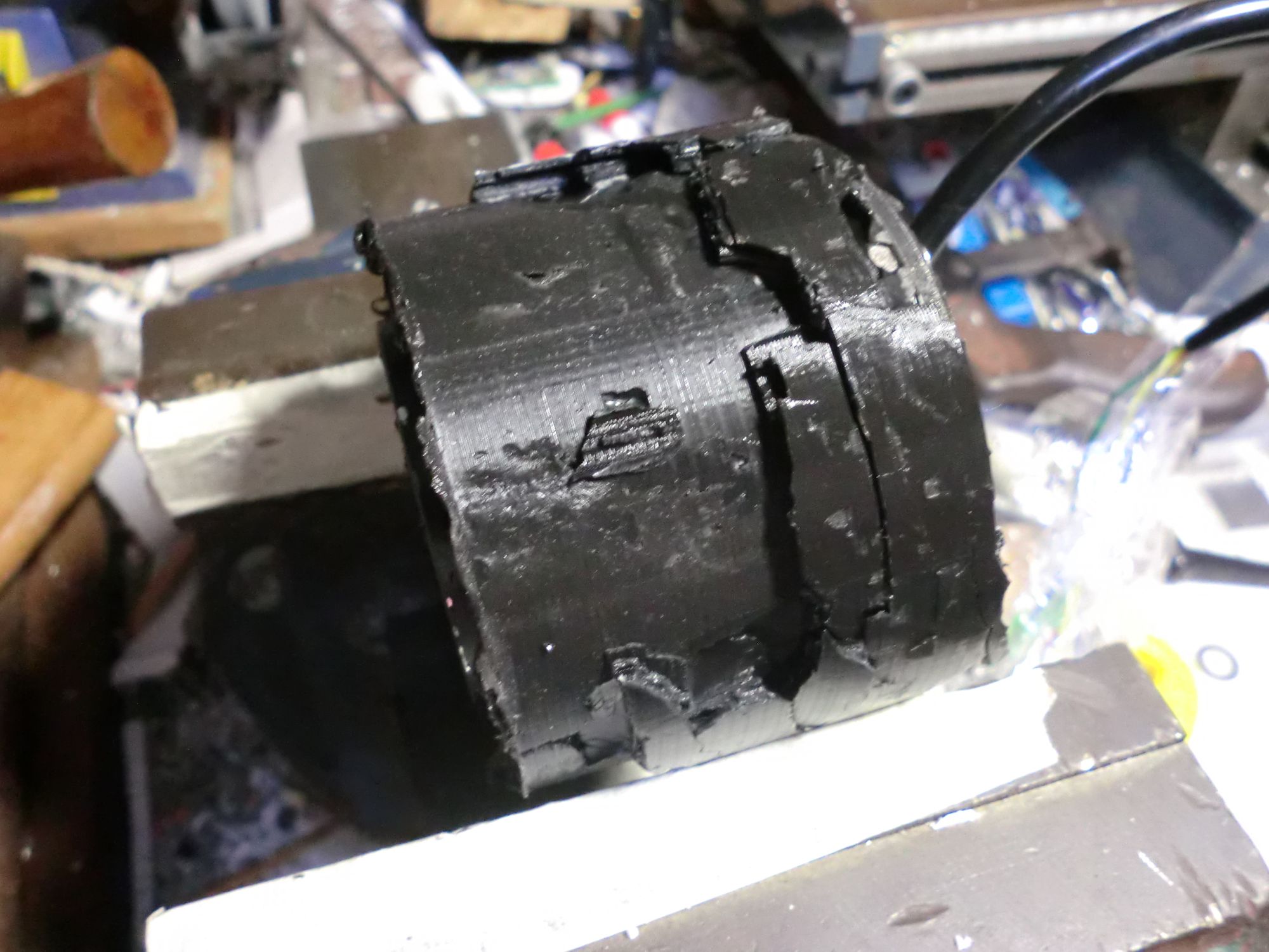
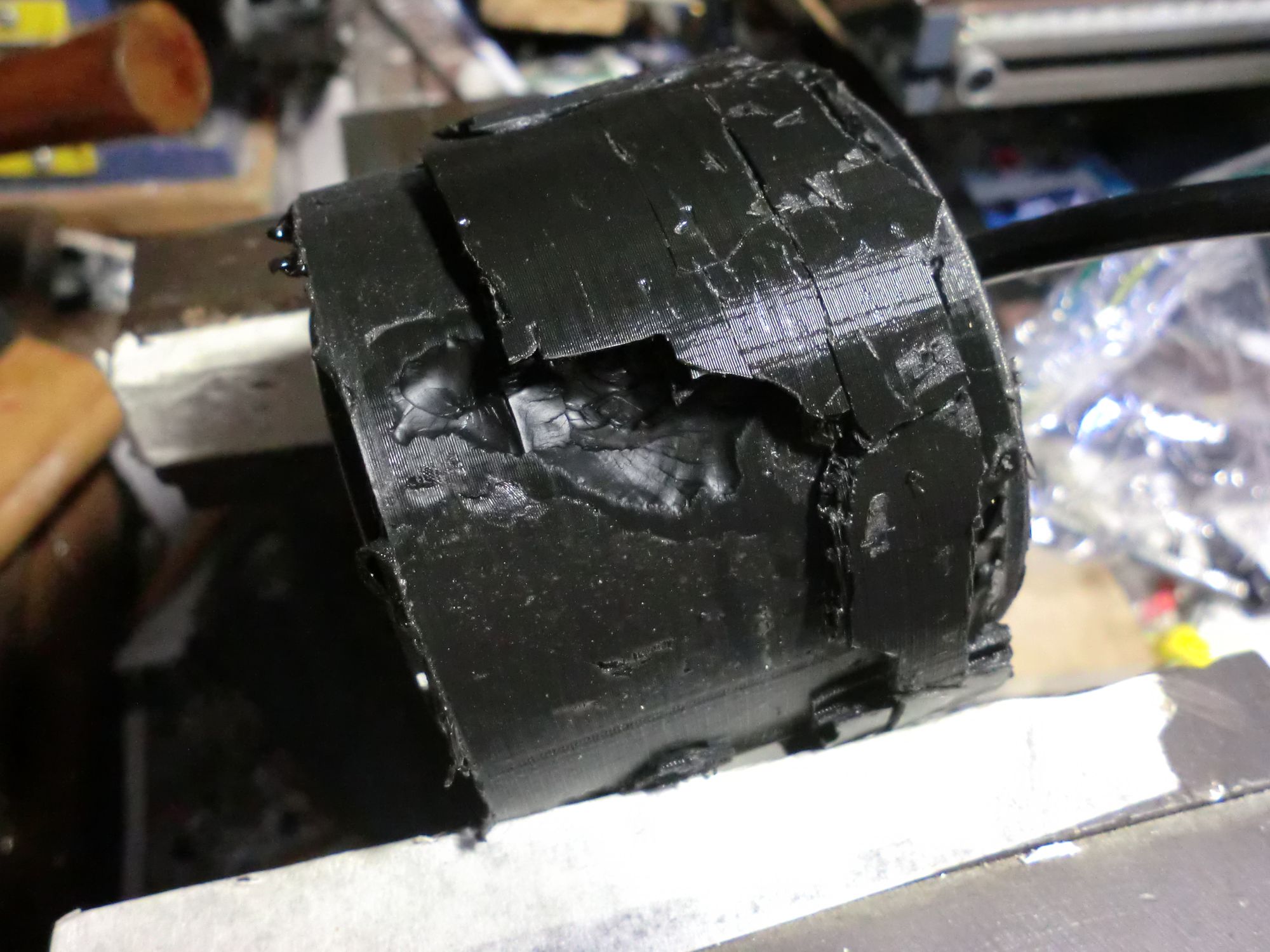
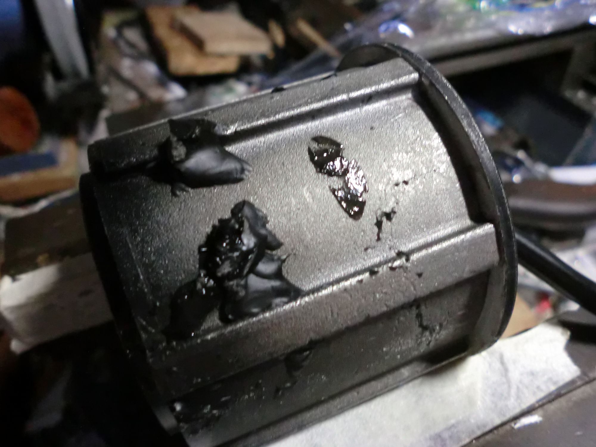
Removal of the silicone "tire" was fun. I ended up having to smash the mould then slowly scrape off the silicone. A wire brush was useful to remove the silicone from the corners of the hub motor. Interestingly, the casting containing corn starch was almost fully dry after a week, while the casting without corn starch still had large pockets of wet silicone.
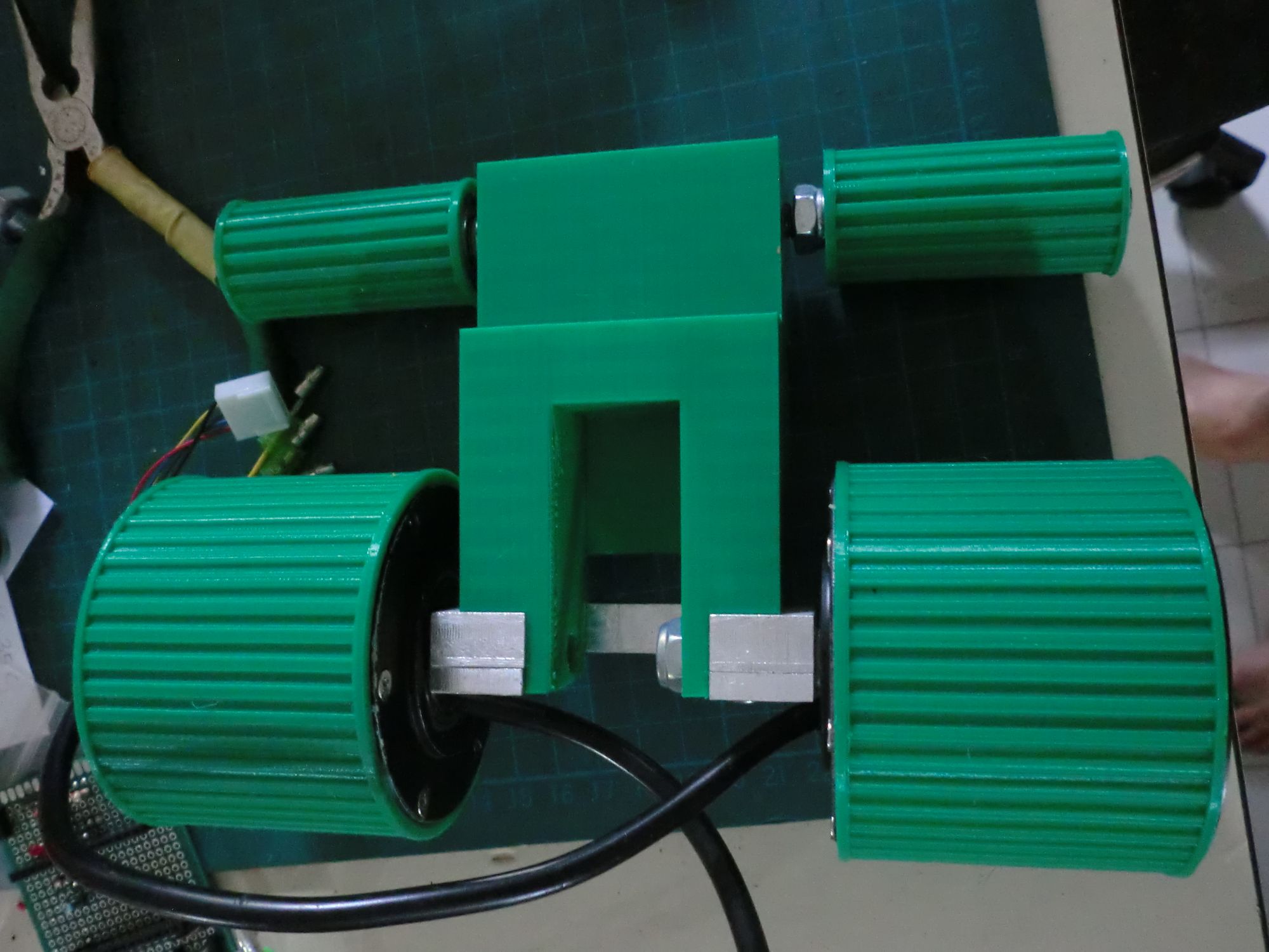
Tracks
After watching videos of past SRG competitions, I realised that many of the competitors used tracks. This is probably because the arena is not magnetic, so the use of magnets to increase the traction of the robot is not an option here. Tracks with their large surface area thus looked like the most viable option.
I ordered conveyor belts and started trying to print sprockets to match the teeth on the belts.
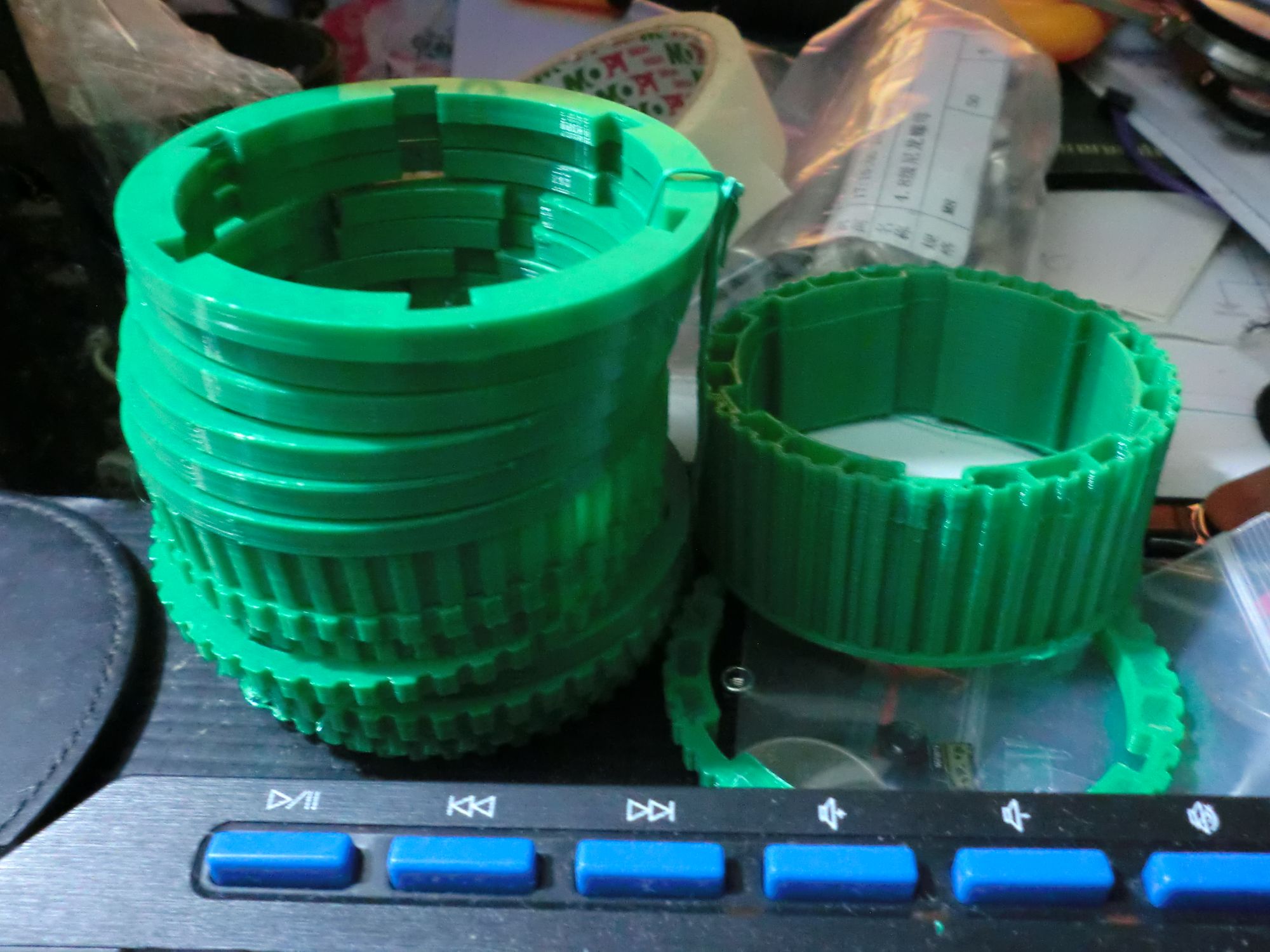
It was surprisingly difficult to match the teeth correctly even after I believed I calculated the dimensions correctly. I ended up having to adjust the teeth count along with the radius of the sprockets to get them to mesh with the belt properly.
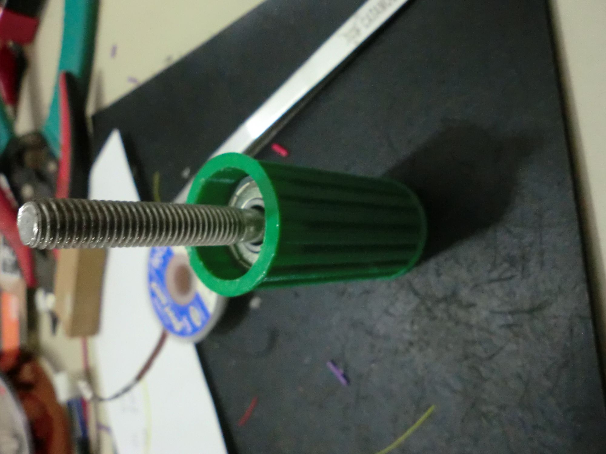
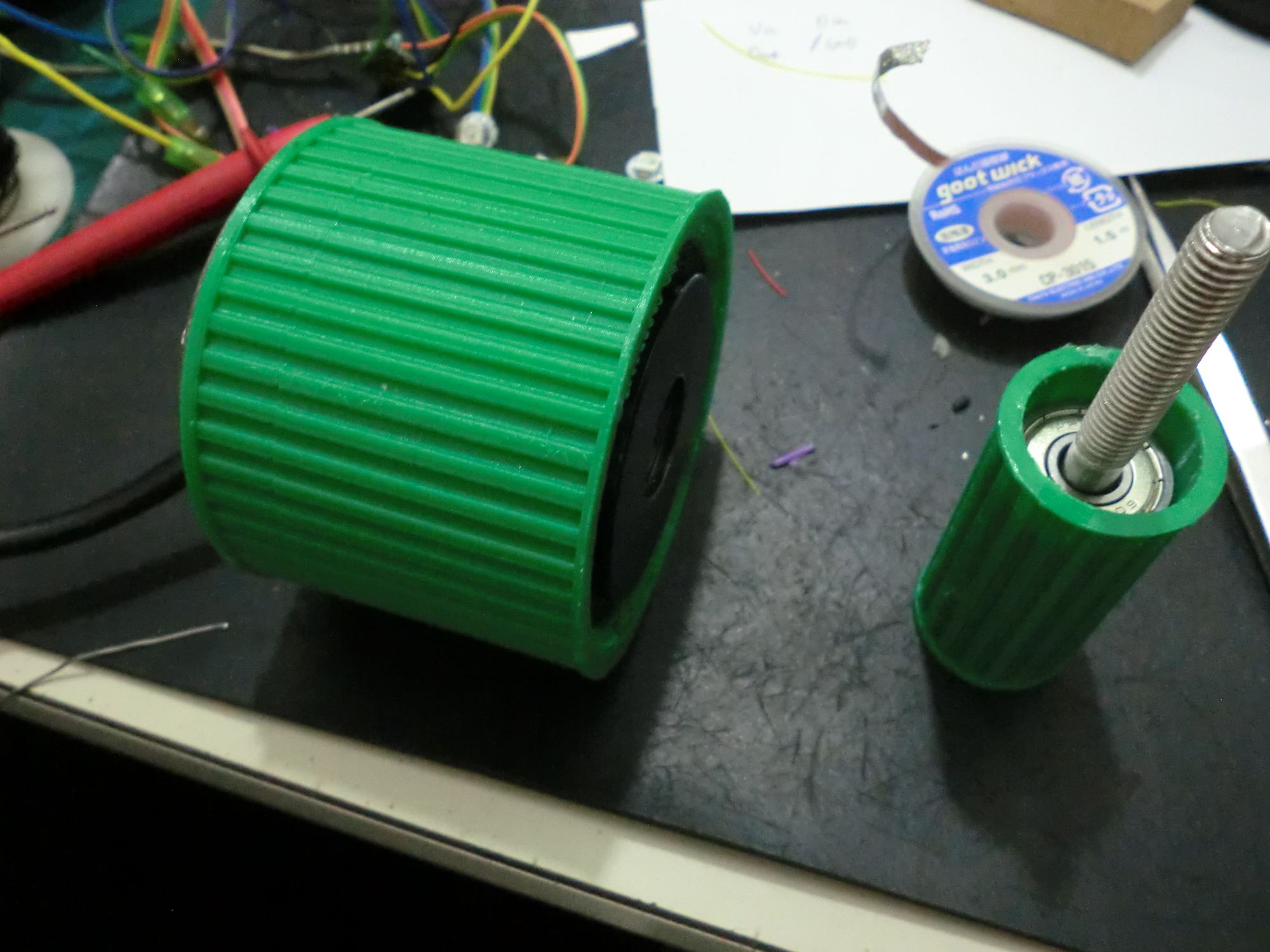
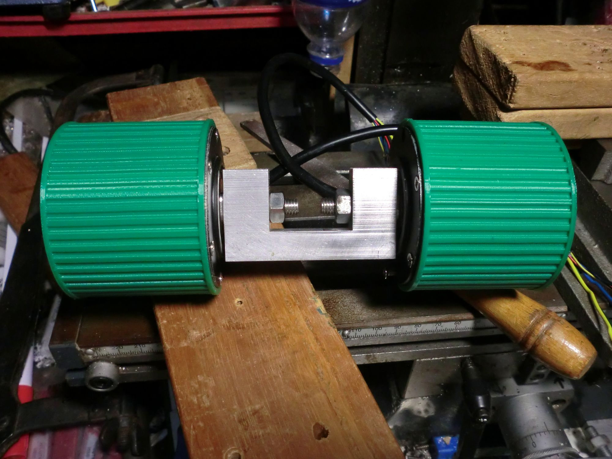
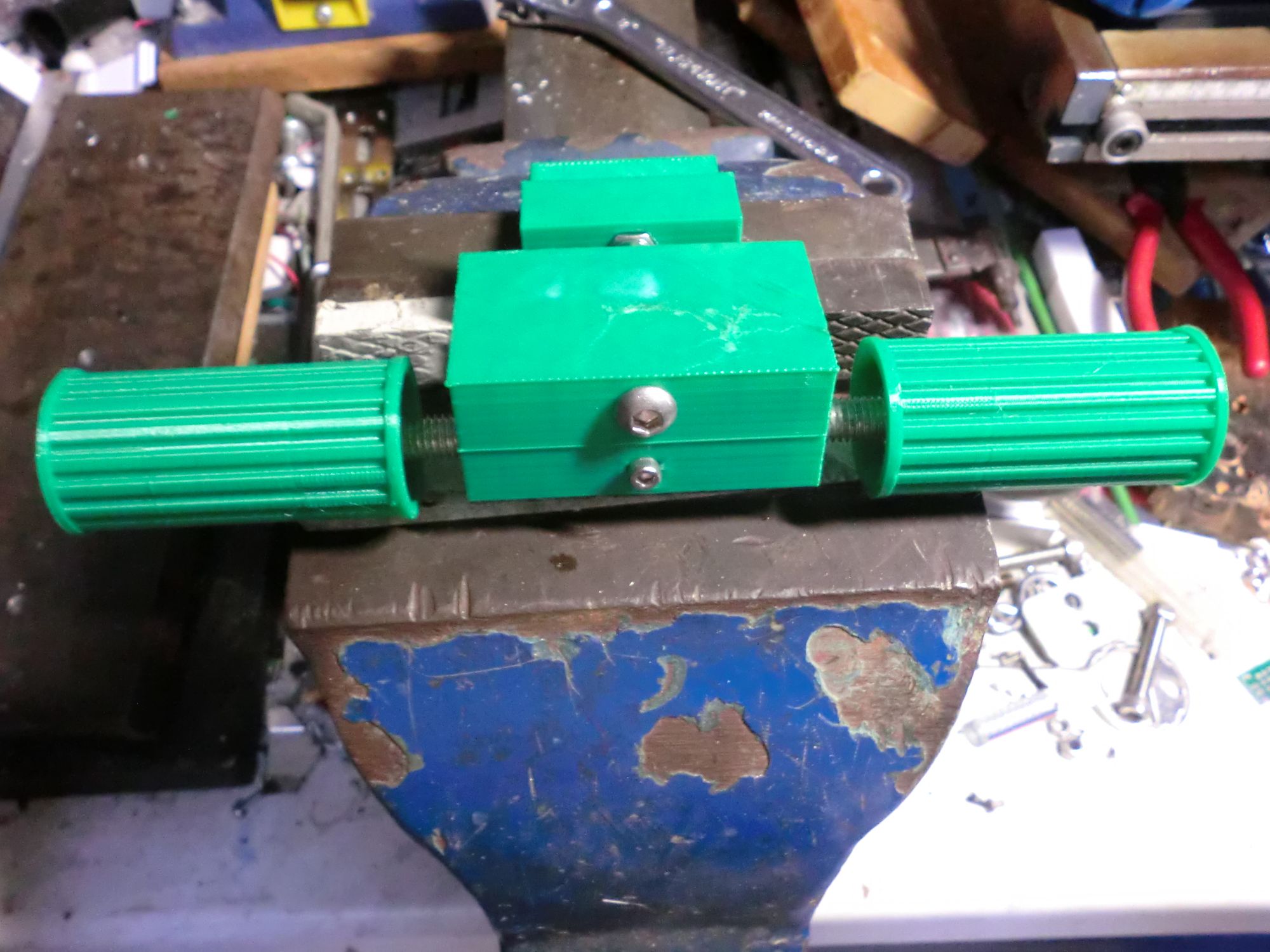
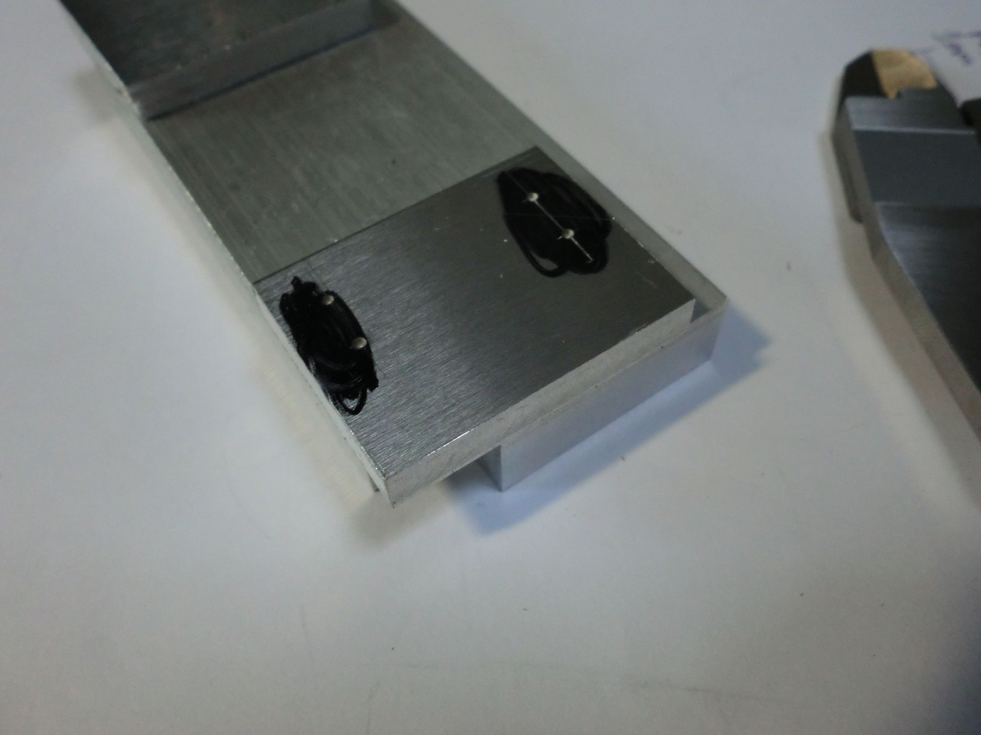
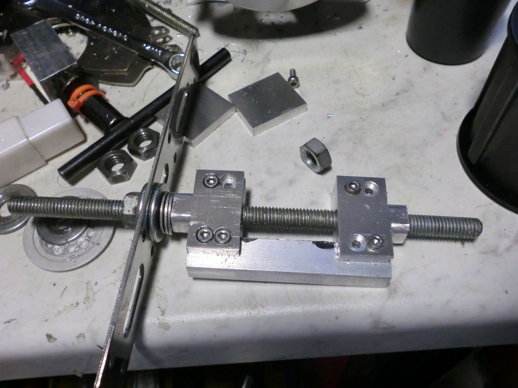
I made use of screws to tension the belt. The larger screw in the photo above can be loosened to apply more tension to the belt.
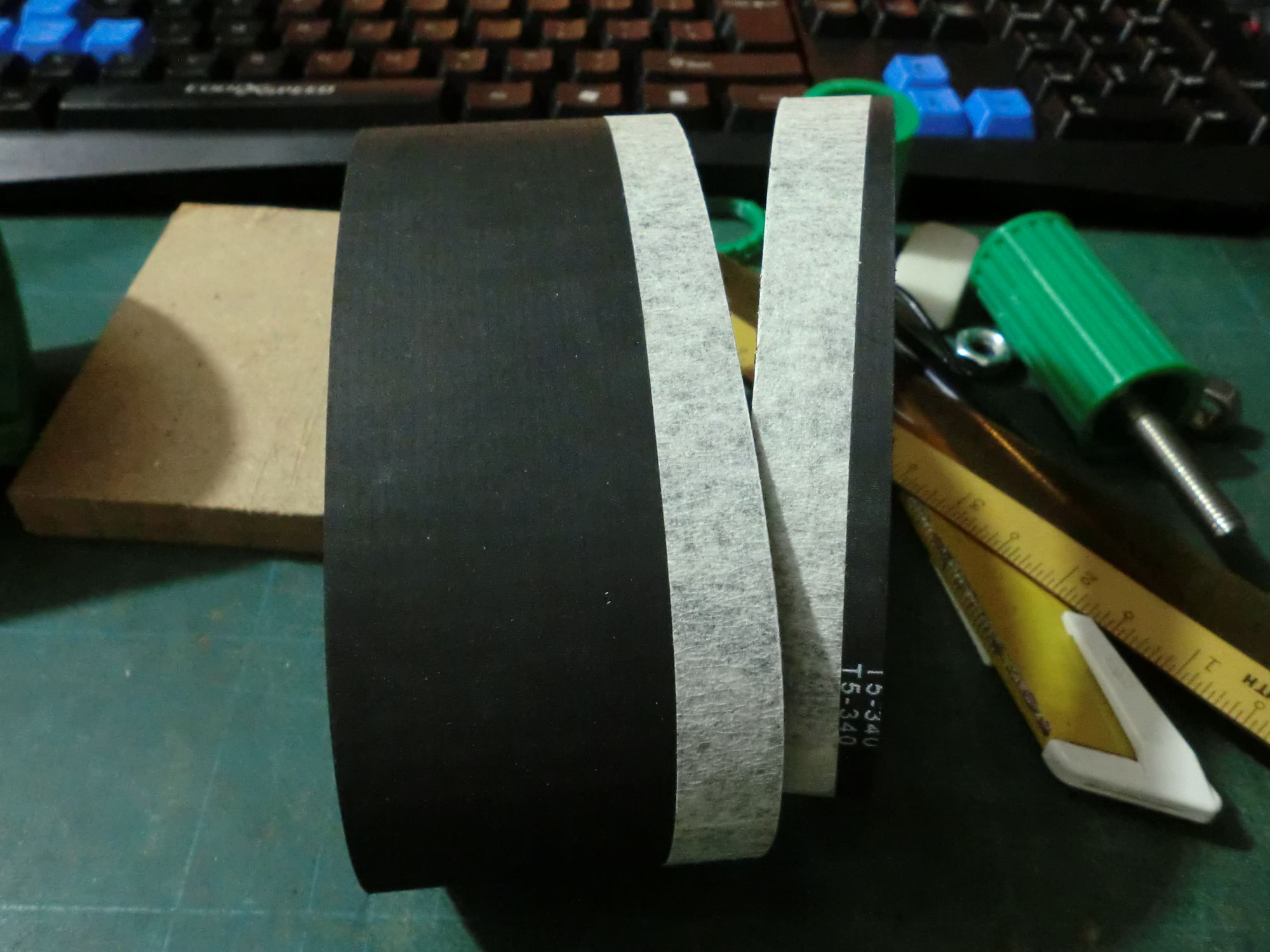
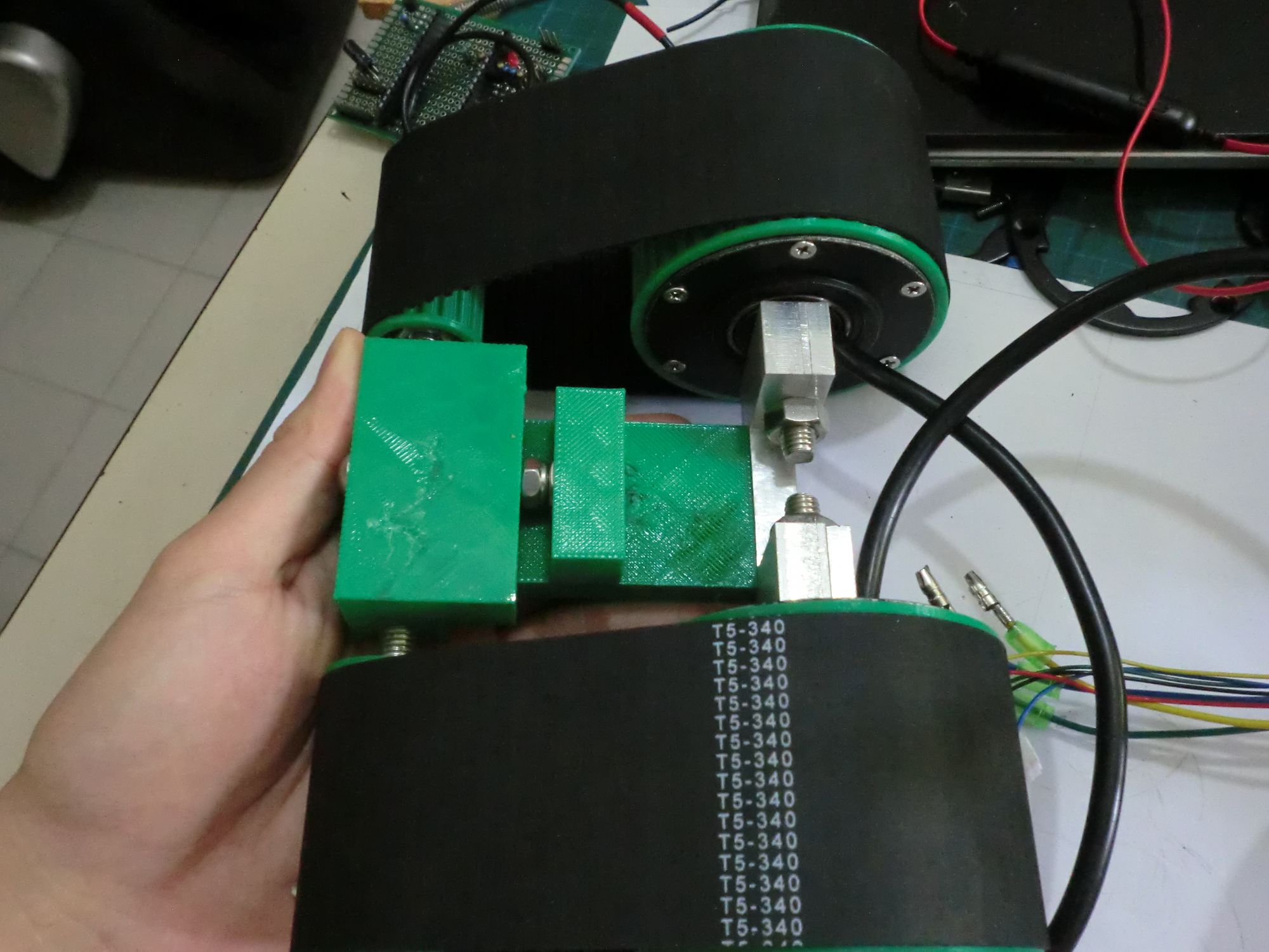
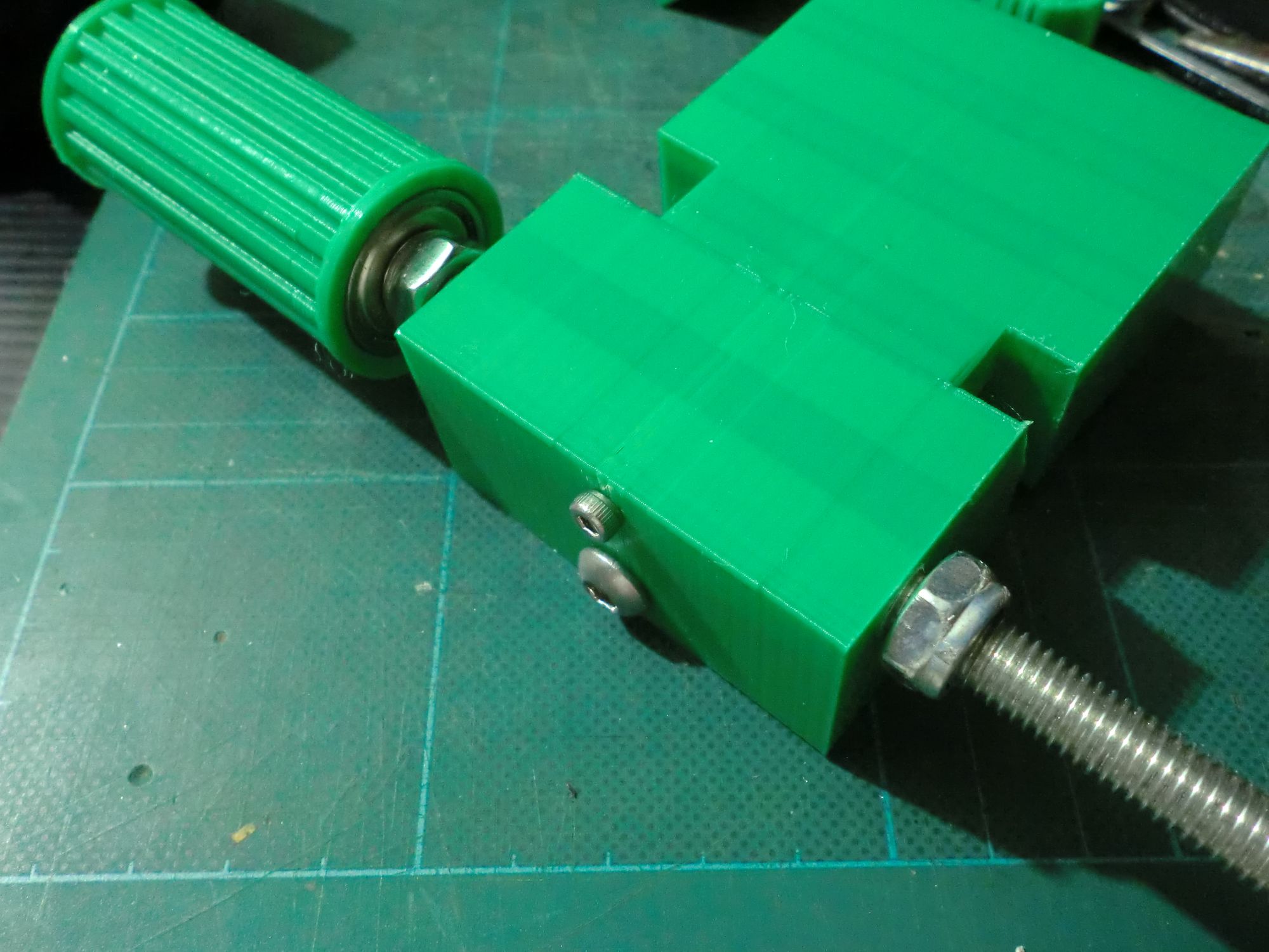
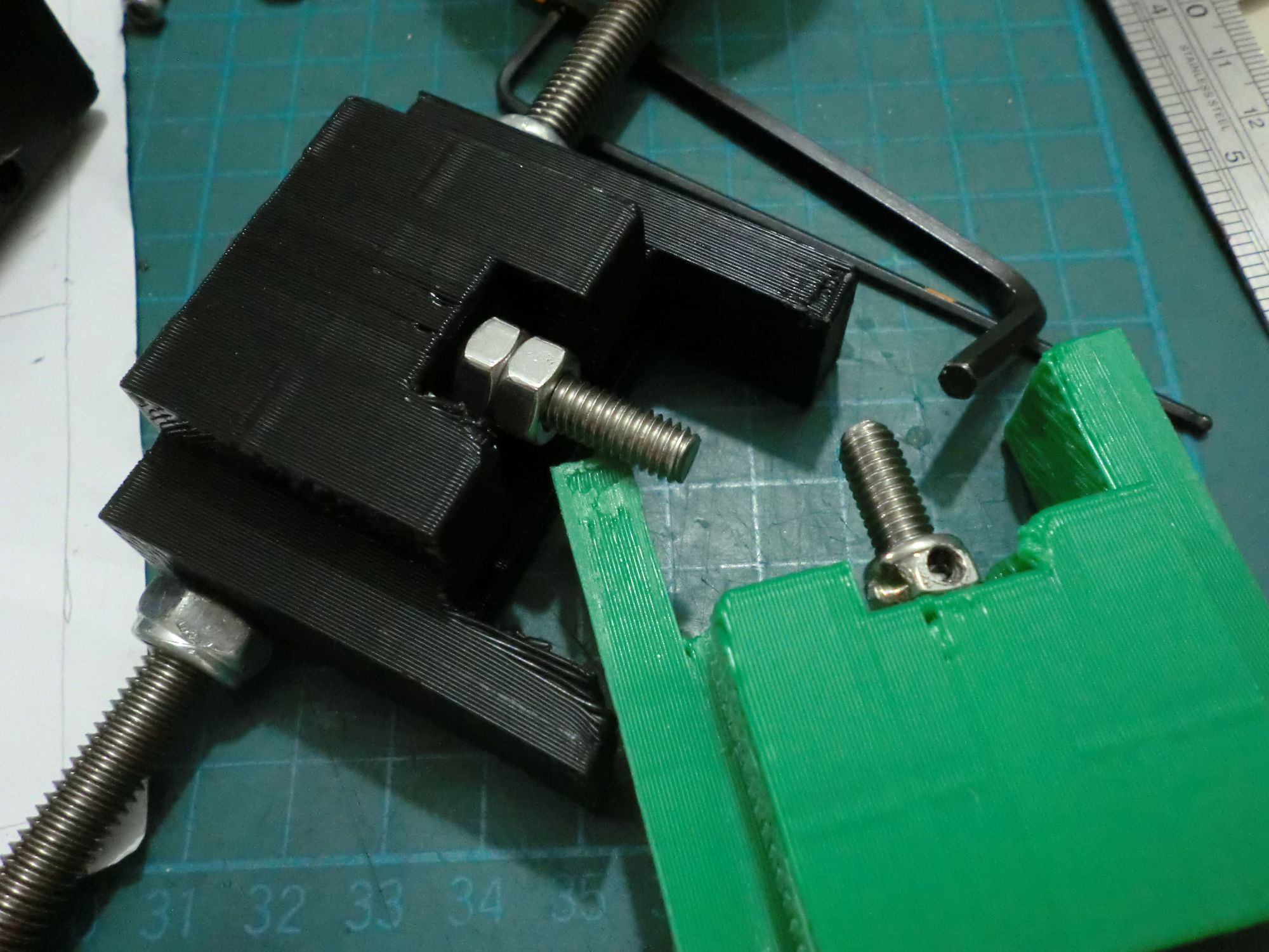
The belt was tensioned by adjusting a screw which forced the smaller sprockets away from the main body. This M6 screw is locked to the piece holding the smaller sprockets. My initial plan of using a nylon locking nut did not work well when applying tension because the nut would turn itself from the friction. I switched to using two nuts forced against each other.
Front Wedge
My inital plan was to use a large paint scraper as the front wedge, reasoning that since it was meant to scrape paint off surfaces, it should be acceptable as a front wedge. I soon found out that cheap paint scrapers are not really flat - they are a thin piece of metal flat only because of the handle.
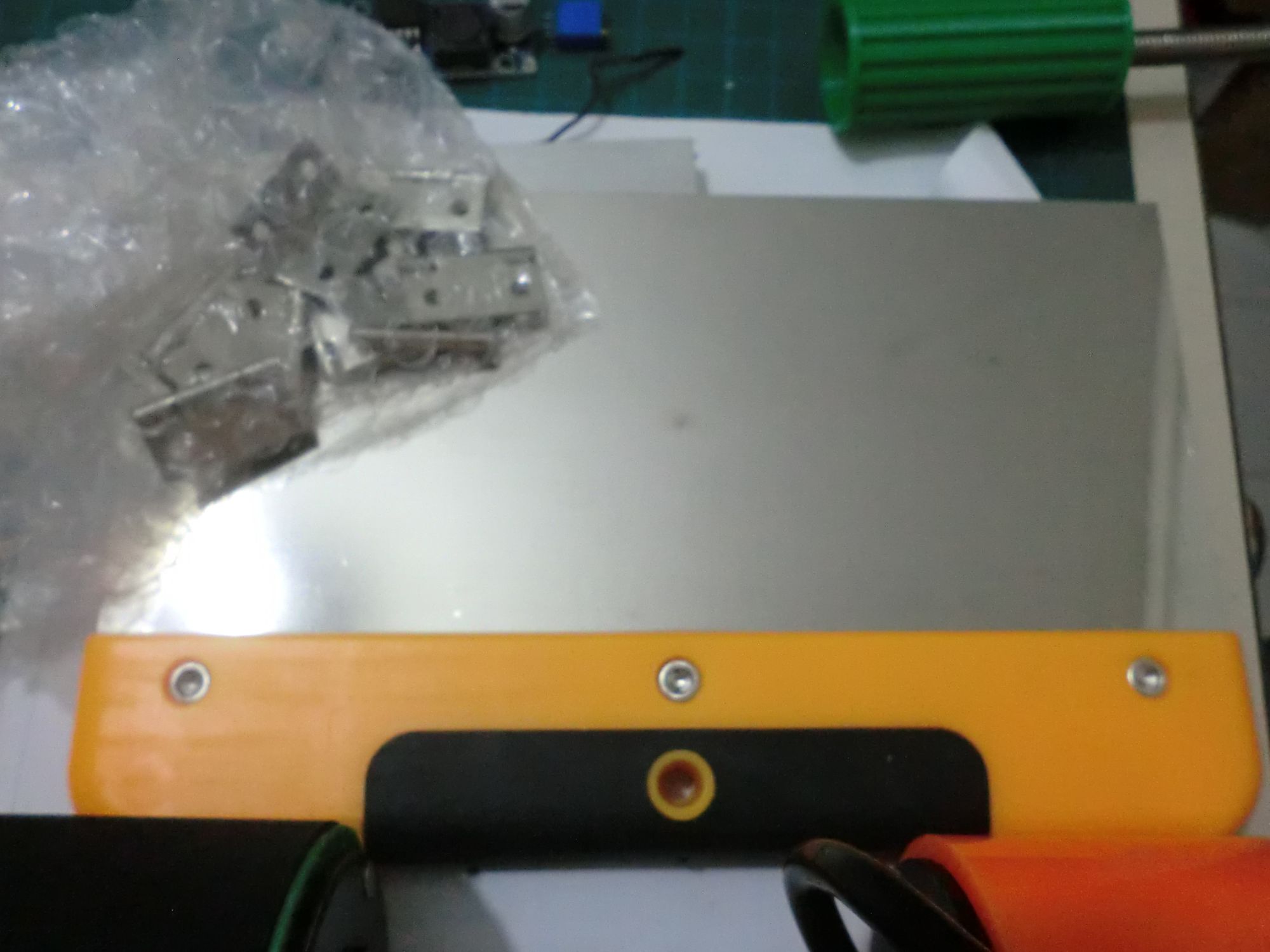
So I did just that, bought 3mm titanium plates and tried to sharpen them.
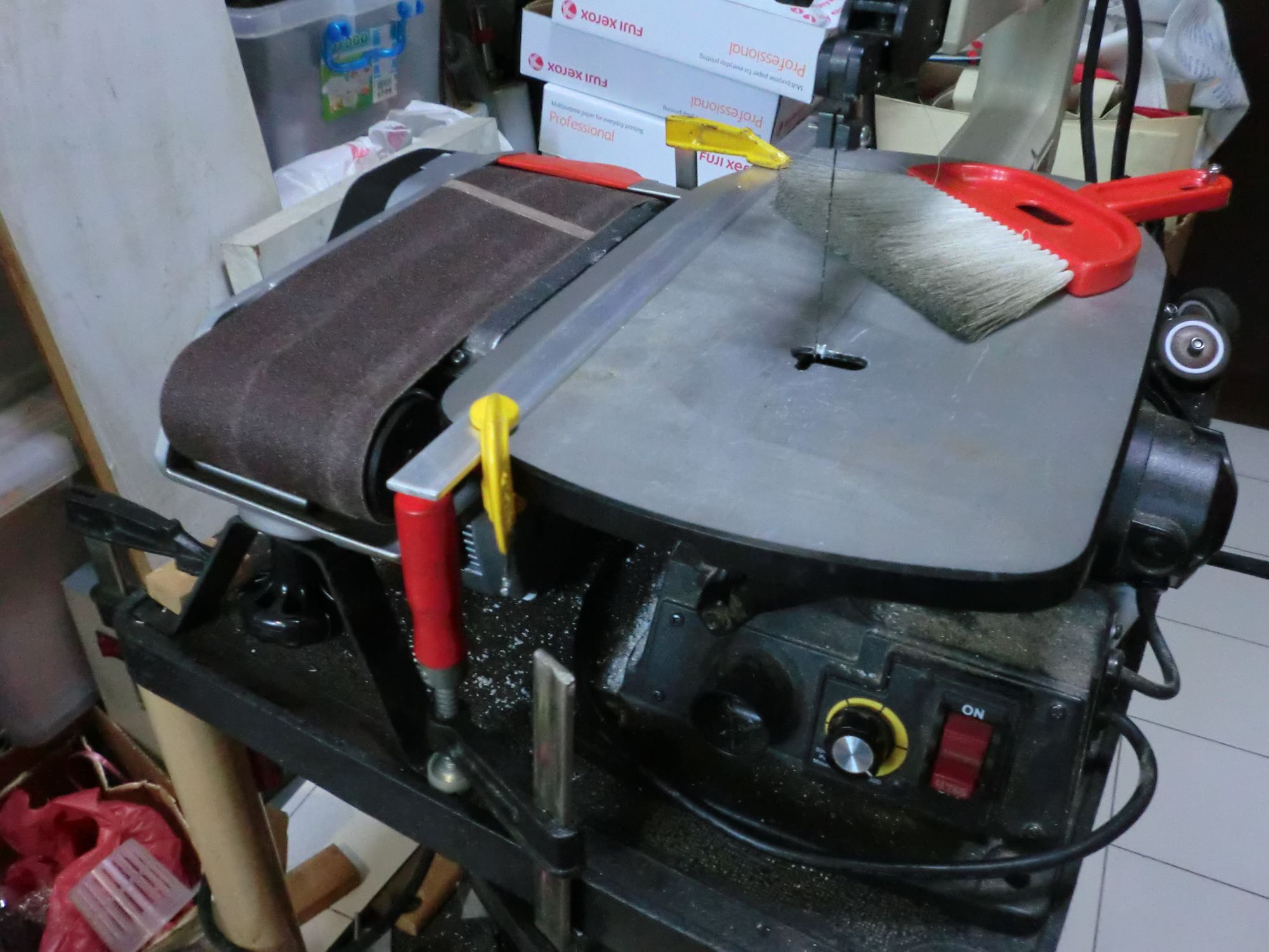
Imagine my surprise when I found out a handheld belt sander does not fair well in this application. I made use of the adjustable table on a scroll saw to try and sharpen the edge of the plate.
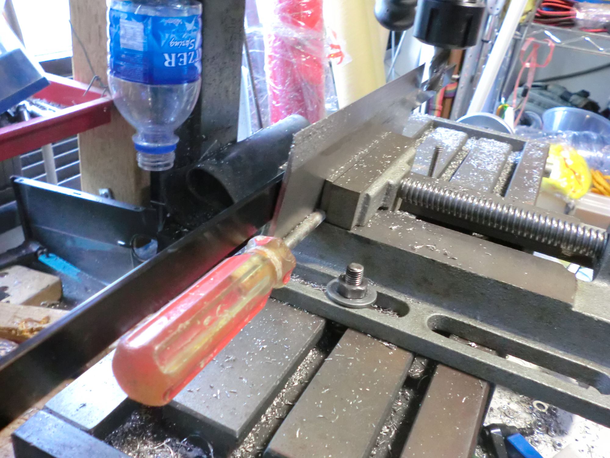
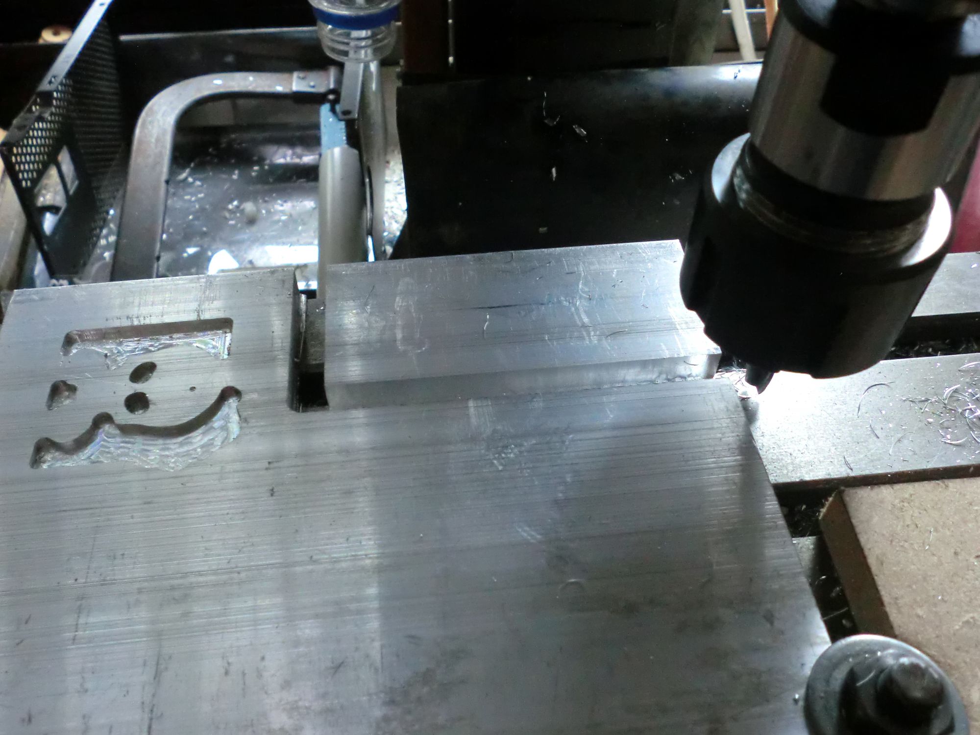
In the end, I resorted to milling down the edge of the plate at an angle to get a rough profile. It actually worked pretty well if you ignore the part where I was adjusting it ever so slightly so that the blade profile would be even on both sides.
The actual wedge is a piece of PVC conduit.
Motor Drivers
In the interest of keeping this as cheap as possible, I decided to use all-in-one electric bicycle controllers to control the hub motors.
In the event you're considering this, please re-think this thoroughly. A whole lot of issues come with this:
- Control - They are not made for the responsiveness you need for the fine control you need with a robot of this size.
- Consistency - it is hard to ensure that you can get controllers with same characteristics if buying from sources like Taobao
- Functionality - the smaller 350W controllers do not come with reverse. The slightly larger 450W controllers which have reverse are of course heavier.
- Voltage - These usually require a minimum of 36V and often come with a low voltage cutoff built-in. It is possible to modify the voltage divider through which the controller senses the input voltage, but you may burn out the MOSFETS with too low a input supply (gate drive voltage too low)
There is also one large issue with the reverse functionality: you cannot change the motor direction while spinning. This makes perfect sense on a electric bicycle (and a minor annoyance when you as a human can react to it), but a showstopper when put on a robot with open loop control.
I tried to solve this issue through multiple means.
- Monitor the motor from the hall sensors and change directions only when the motor was not spinning.
- Blip the throttle to 0 for a few ms after a change of direction if the throttle is high yet the motor is not turning
Neither of the solutions worked reliably without introducing a very obvious delay when switching directions. In the end, I went with setting the throttle to 0 for a few ms after every change of direction. This provided acceptable performance when combined with the load on the hub motors.
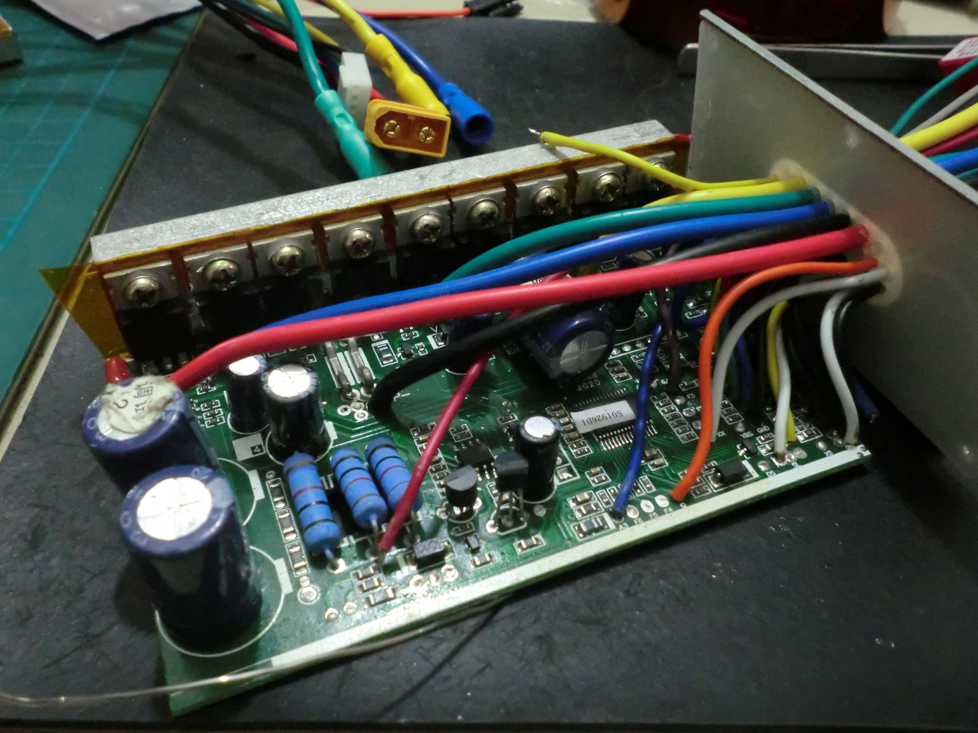
I stripped down the motor controllers to save weight, removing the case and most of the connectors.
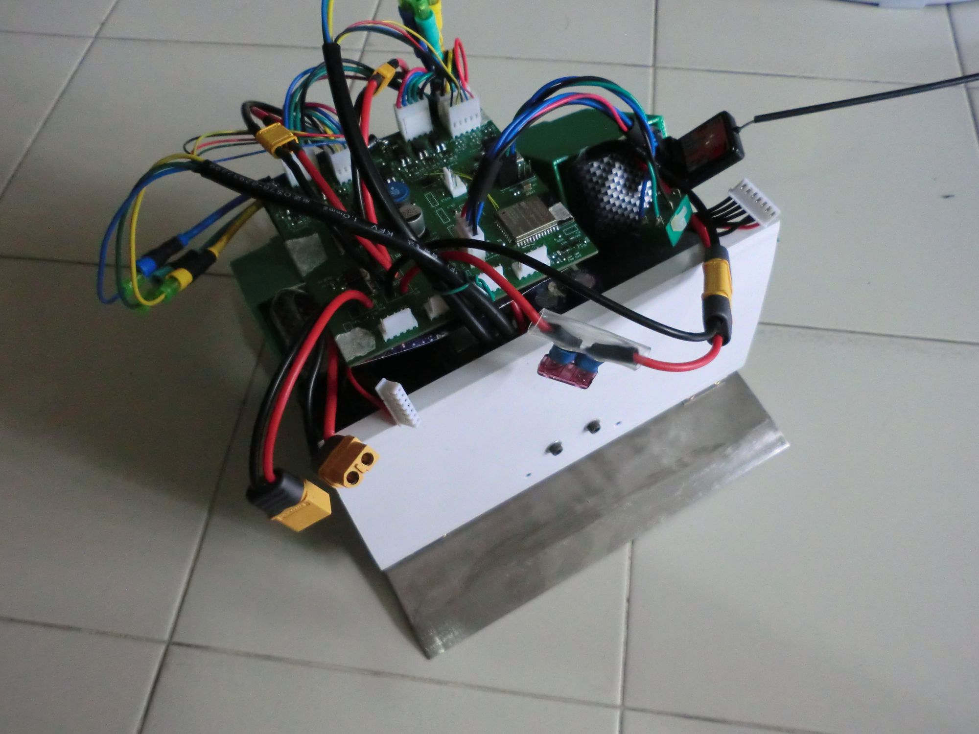
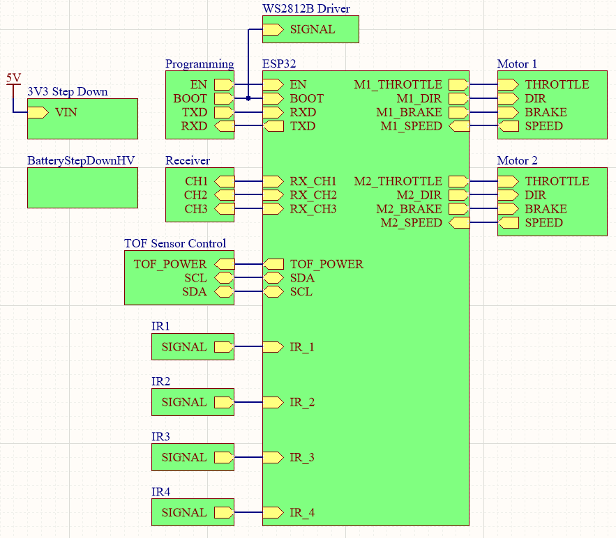
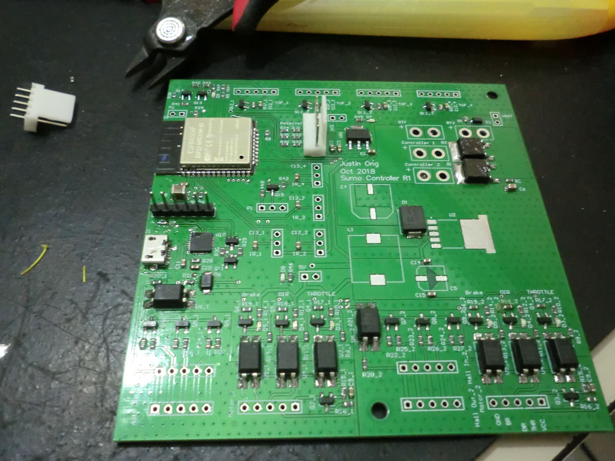
Electronics
I designed a custom PCB around the ESP32 to control the robot. The Altium project files can be found here. Note that there are some issues with the bootstrap pins that I had to correct manually, read this clearly.
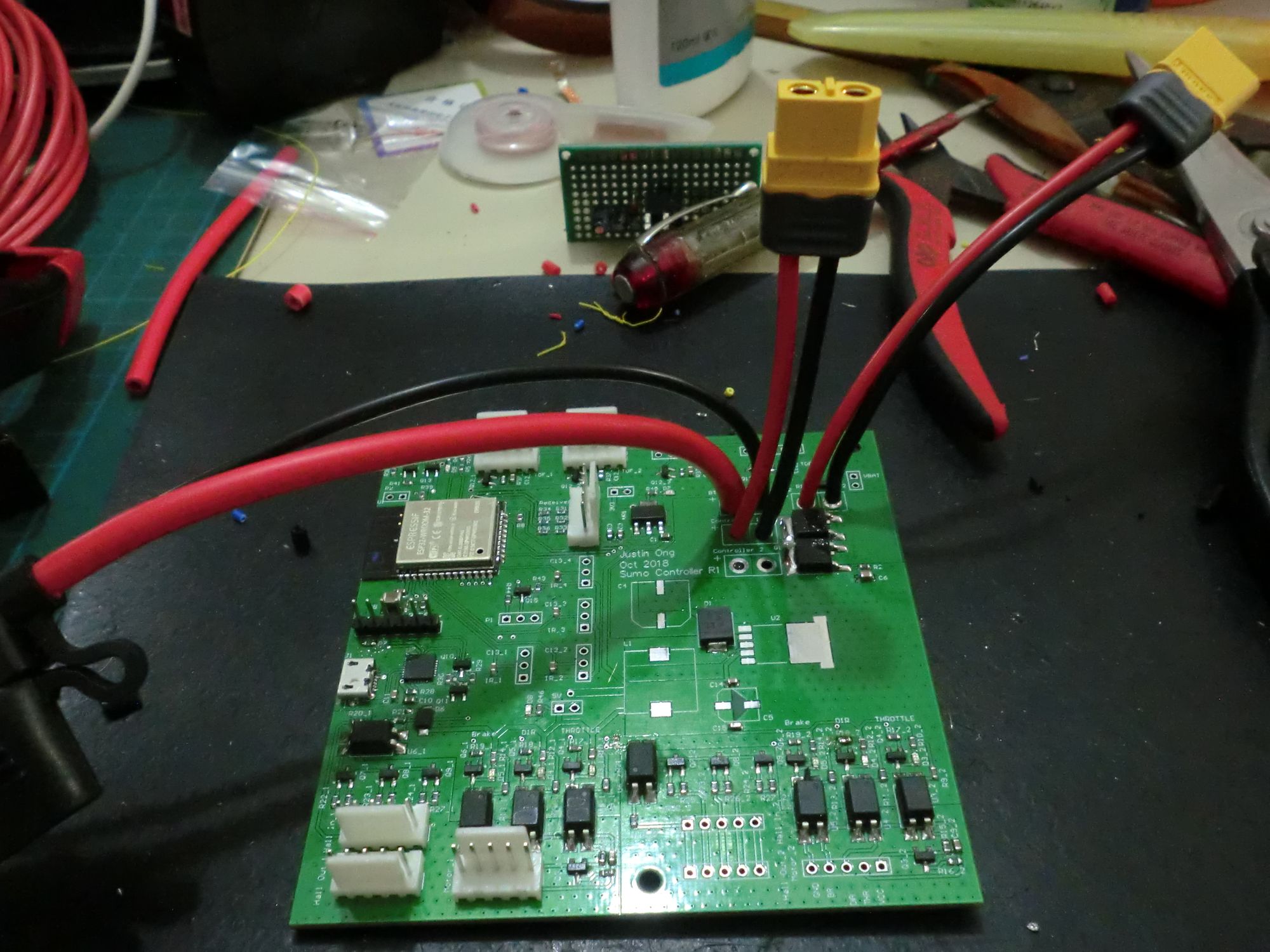
Power
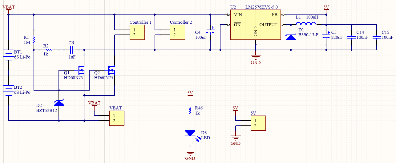
I decided to step down the battery voltage to 5V because the receiver operated at 5V. The LM2596HVS was chosen as it was one of the only high voltage high current (3A) buck converters available (and it had components and layouts in the datasheet I could just copy off) just in case I decided to power LEDs off the 5V rail. It was also available on LCSC (and went out of stock between me designing and placing my order).
I also tried to build in an anti-spark switch to prevent sparking at the battery connectors when connecting batteries (high current spike due to the large capacitors on the motor controllers). However, this did not work in practice and I just let the connectors spark, will probably have to change them in the future once the pins are too badly damaged.
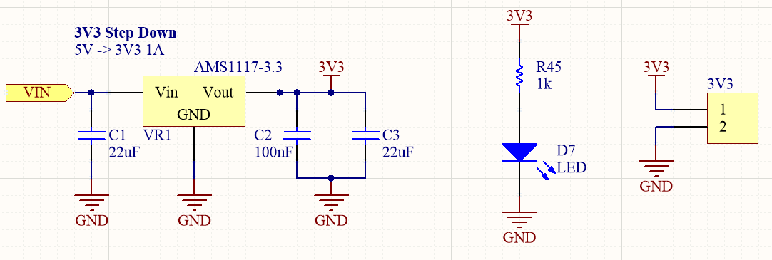
Standard AMS1117 LDO step down.
Programming Interface
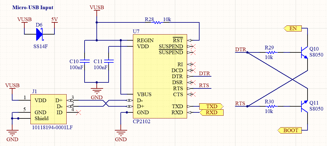
Standard ESp32 programming circuitry.
Receiver
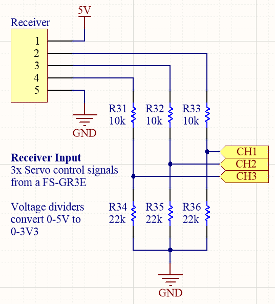
The standard RC receiver that I used operated on 5V and has to be lowered to 3.3V (the ESP32 is not 5V tolerant).
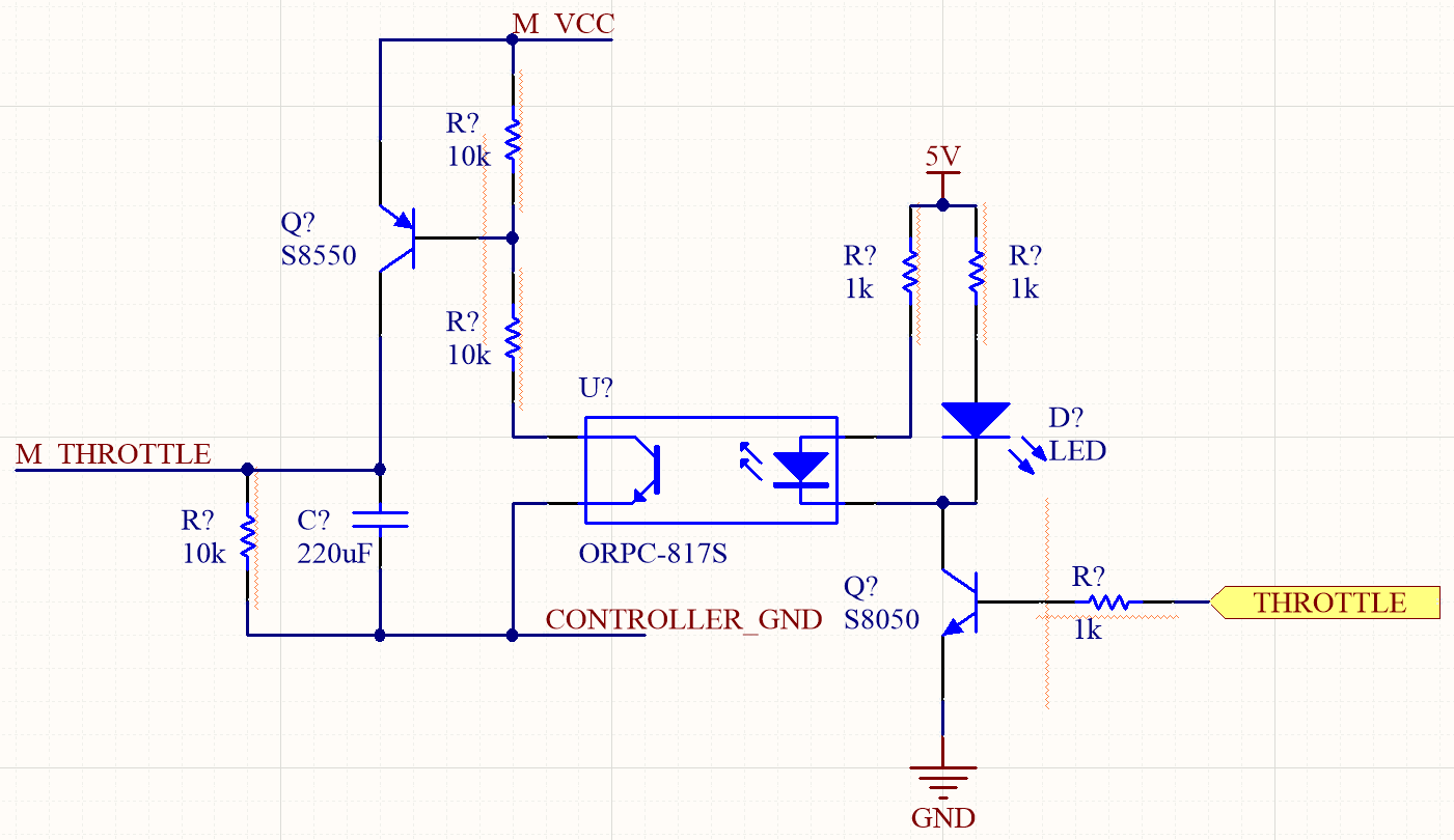
Motor Controller
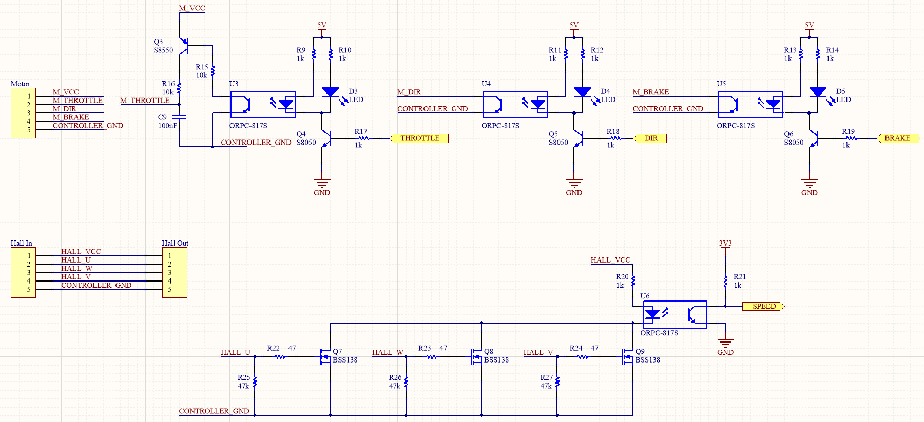
This part was probably completely overkill and not necessary, but the entire interface with the motor controllers was isolated from the microcontroller.
M_THROTTLE is meant to be connected to a potentiometer. C9 and U3 was my attempt to create an isolated variant of the "low-pass filter a PWM signal" crude DAC, but did not work well as C9 was charged but had no way to discharge. This differs from the push-pull nature of a GPIO pin. I was also missing a pull-up resistor on Q3. These issues were fixed on the PCB. I probably should simulate these things before sending the design out for fabrication.
The circuitry below attempted to OR the hall effect sensors to increase the number of edge transitions for motor speed tracking, but after testing, I realised that just one sensor is enough as there would be transitions on every sensor at the same time. This was built to try and resolve the direction switching issue, but was not used in the end.
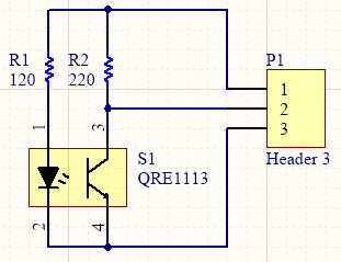
Line Sensors
Nothing much to see here, this is my own variant of the QRE1113GR-based line sensors with reference to these.
Proximity Sensors
I used VL53l0X modules on the front of the robots to sense the opponent. These modules share a common I2C bus with a caveat - they listen on the same address on startup and can be changed with a I2C command. The manufacturer has published an app note suggesting that a single GPIO pin be allocated to each module's reset pin, then enabling the modules one at a time and changing the address accordingly.
I tried something else - putting a RC circuit on the reset pin of each module such that the sensors would be enabled sequentially with a different delay on each module.
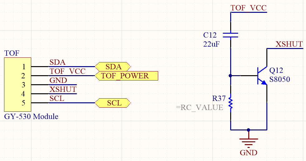
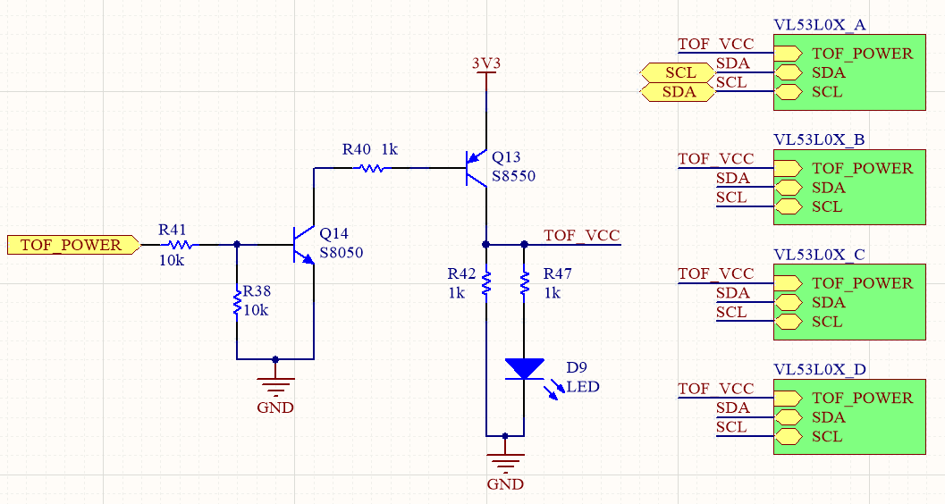
I added circuitry allowing me to control the power supply to the modules just in case I needed it - these turned out to be a great idea as the modules often failed to initialize properly. I suspect issues with the RC circuit, but am unable to confirm as I do not have a oscilloscope.
I took the lazy way out, restarting the initialization sequence and power cycling the modules if they did not start properly.
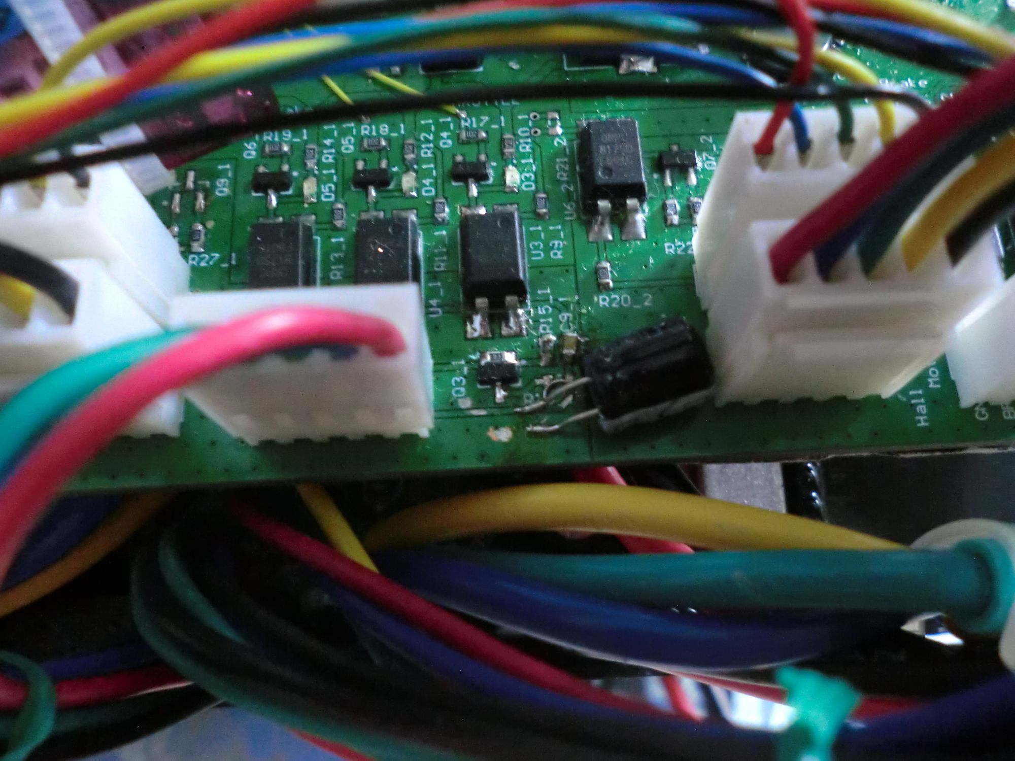
PCB
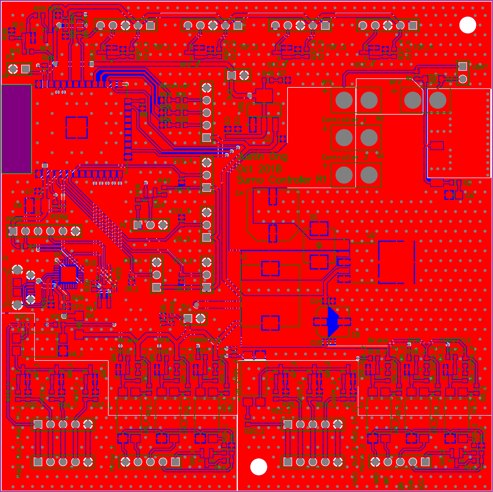
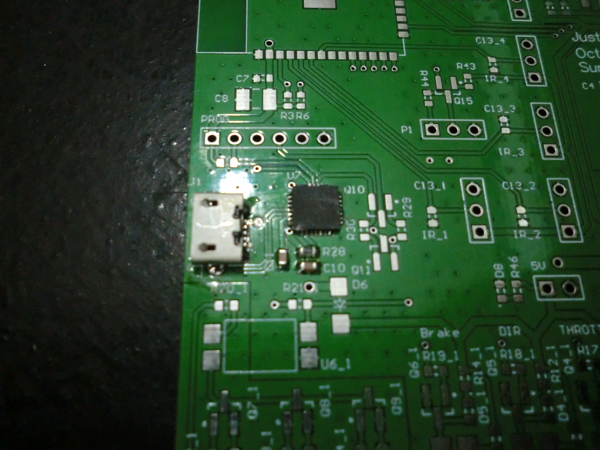
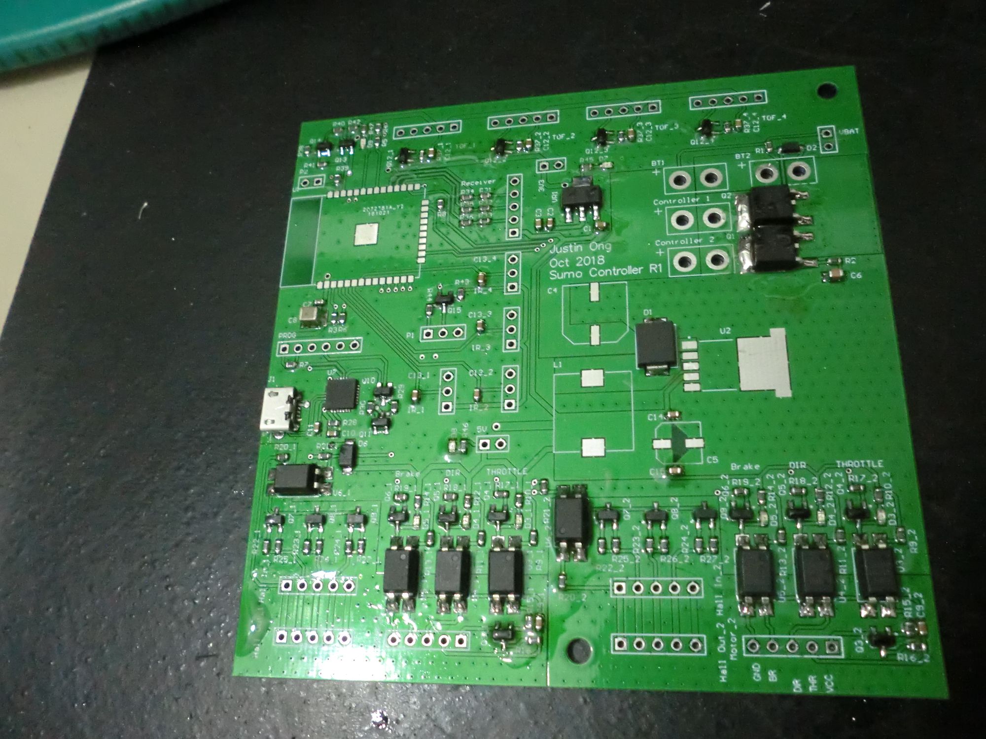
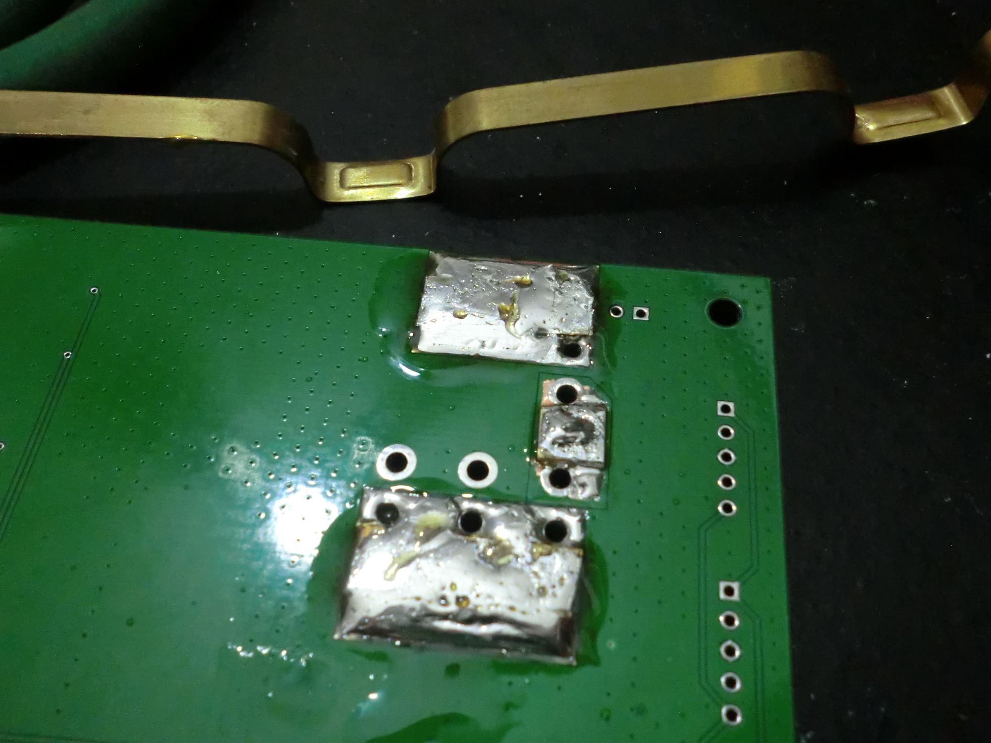
The PCB was hand assembled, surprisingly soldering the QFN CP2102 with flux and hot air was quite straightforward.
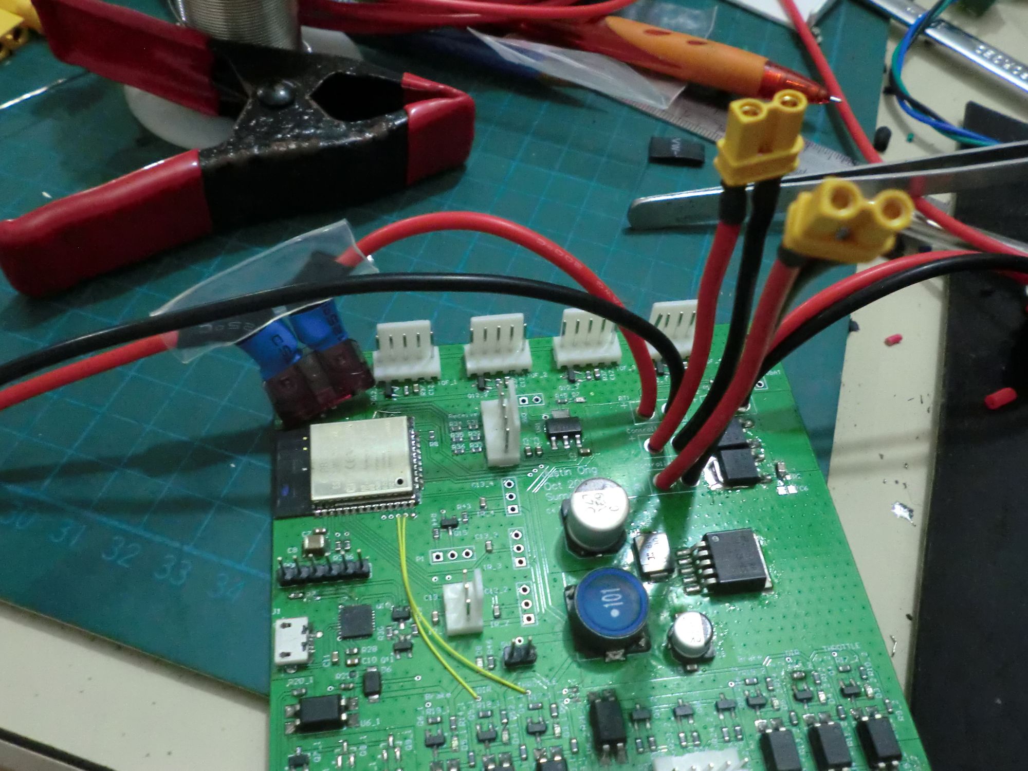
Note the yellow wires, I decided to switch the GPIO pins controlling throttle and direction because the pin for throttle wasHIGH when programming the ESP32 - having one wheel spin to full speed suddenly when programming is alarming.
Weight Loss
Between the 1400g of motors, 400g of motor drivers and 500g of batteries, I had roughly 700g for everything else on the robot.
I went after the metal parts first since the plastic 3D printed parts were already quite light.
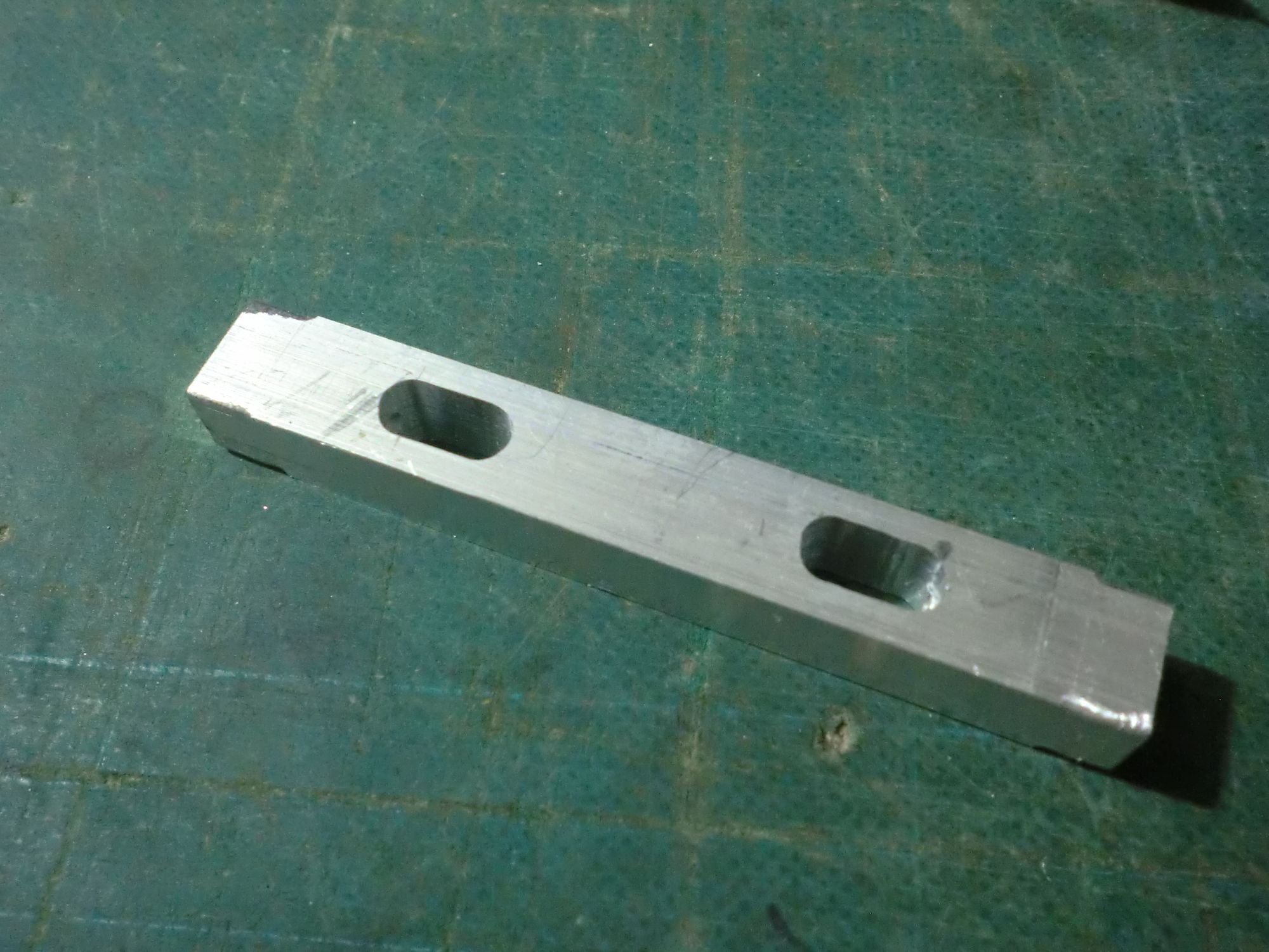
Motor Mount
My initial motor mount was quite large because I thought I had to fill out the full 12mm mounting hole in the motor, forcing me to bolt together two plates to get the required thickness. This was also because of the M8 hole in the motor.
Initially, I tried switch to a titanium M8 rod to lighten the rod. This saved me 30g.
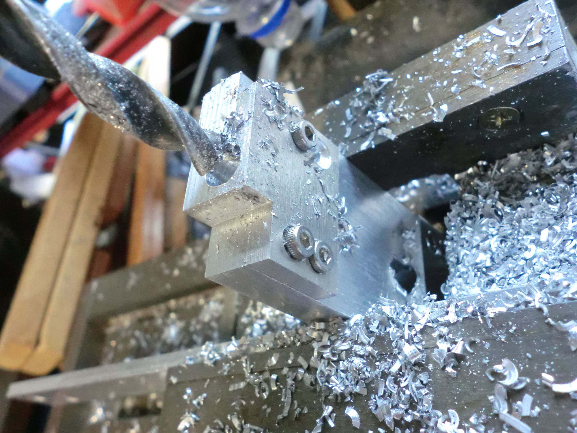
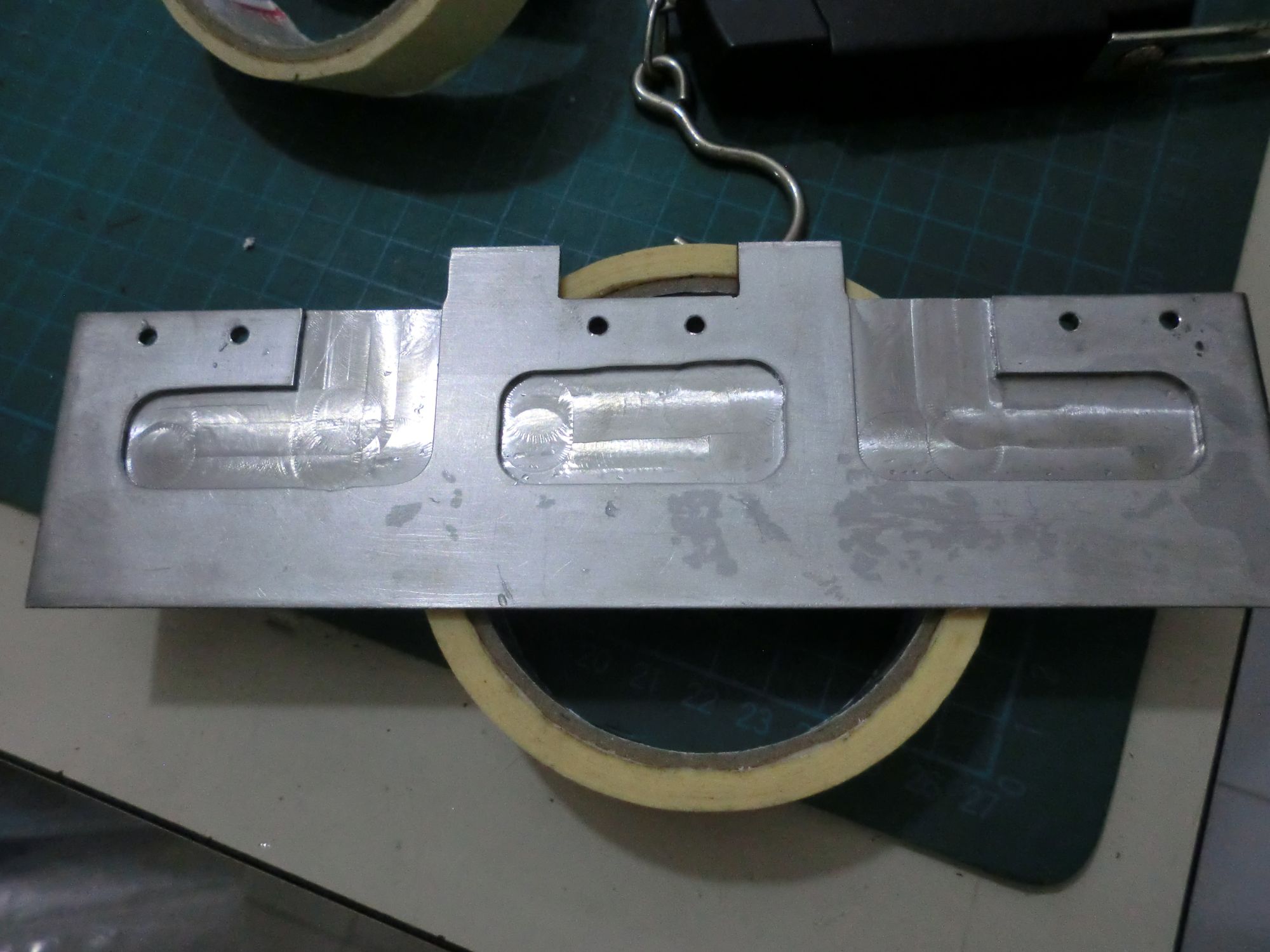
What if I didnt need the strength of a M8 screw? These motors came with a M8 mounting hole because they're meant to take the weight of a human, but in this case, its just a extremely light 3kg robot. I redesigned the mount with this in mind, using just M3 screws to hold the motors to the mount.
The next obvious target is the front wedge - in hindsight 3mm was much thicker than what I needed.
This was just barely enough, my robot was something like 2995g when weighed before competing.
Conclusion
As mentioned at the beginning, my robot didnt't do too well (or practically, did terribly), losing at the second remote controlled round and at the first autonomous round.
I'll hopefully be back next year with better results.
Lessons learnt:
- More traction
- Stop being a cheapskate and use proper motors and controllers
- Find a more efficient way of seeing the opponent for autonomous mode - maybe a camera?
Regardless, it has been really fun to scratch that itch and get back into building.