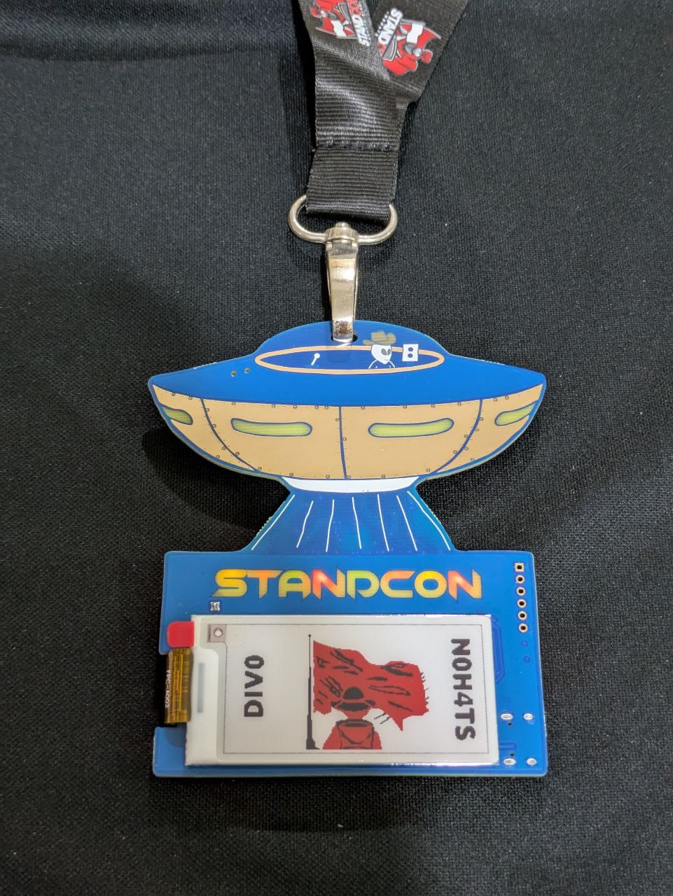
STANDCON 2025 Badge
Building a electronic badge has been on my TODO list for quite a while, and I jumped at the chance to build one for STANDCON. The idea has sat in a corner for so long partly because I've always wanted to do more than just a few blinking LED, so how could one build some depth into a badge?
Building challenges are hard too since I categorise hardware challenges into two extremes: the deep end of unknowns requiring substantial equipment and knowledge, for example, power line glitching or reverse engineering/exploitation of relatively obscure architectures with poor tooling. The other end is dominated by application-level bugs that can be trivially deployed digitally rather than on custom hardware. The Internet-of-Things, commonly joked about as a trivial way to pad one's portfolio with CVEs, often involves exploitation of some out of date Linux installation that would barely qualify as a entry level challenge in a CTF.
With these in mind, I decided to focus on hardware communication protocols as a middle ground - hopefully approachable enough to convince software-focused people into trying the challenges, perhaps finding out that hardware isn't that foreign and magical.
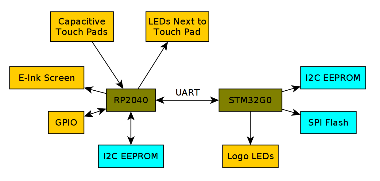
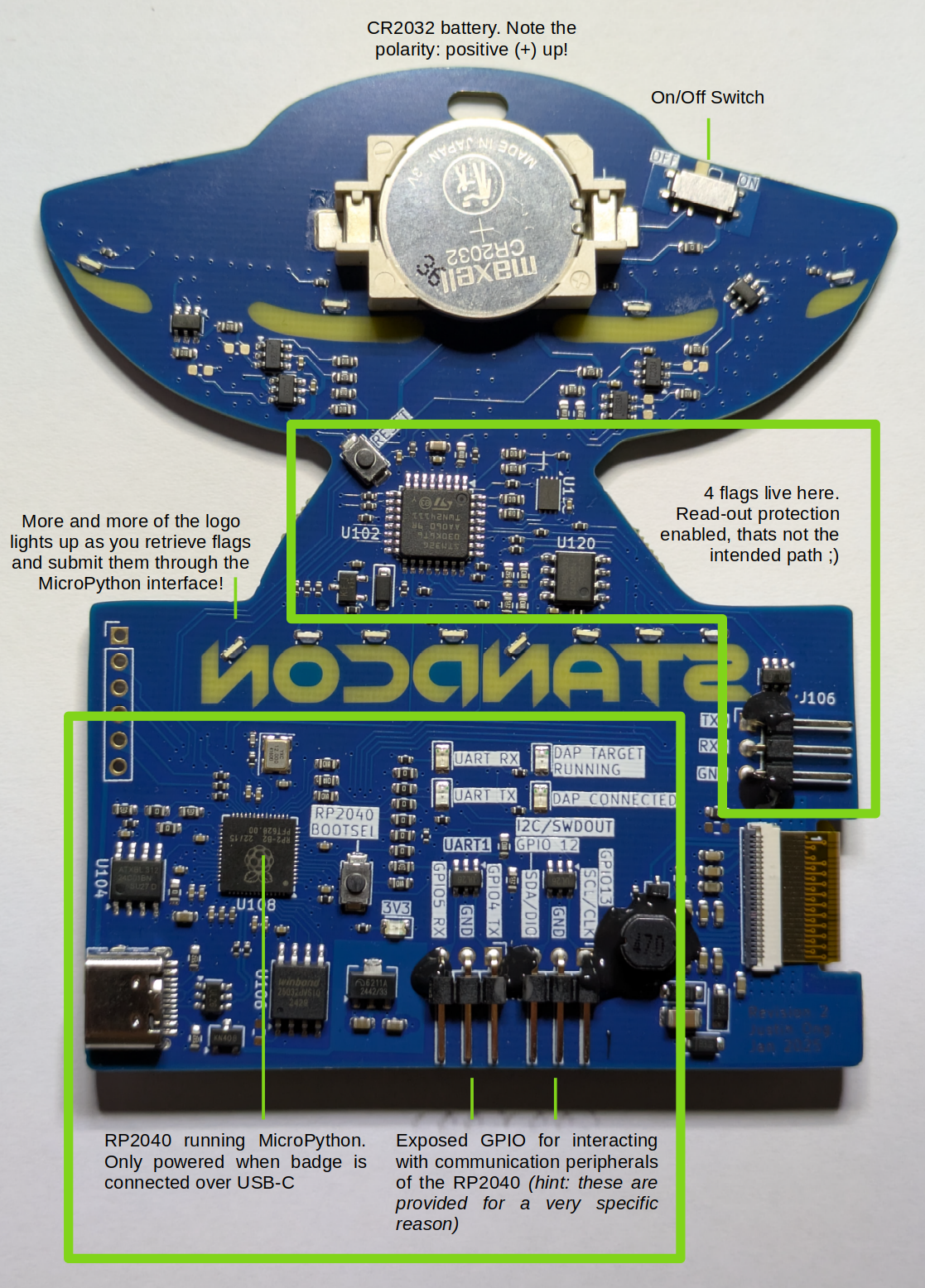
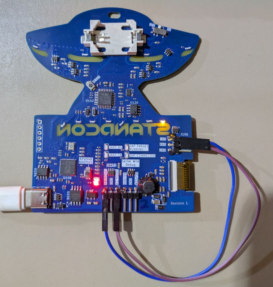
Trying to prevent the badge from turning into electronic waste after the conference was also another consideration. I tried to address this in two ways: adding a electronic ink screen to the badge (at quite the expense to the bill-of-materials!) hopefully for people to write their name on and reuse it in the future, and leaving the badge usable as a swiss army knife for interacting with other external hardware. The Raspberry Pi Debug Probe being built around a RP2040 presented a interesting idea - what if I used a RP2040 and exposed the same set of GPIO pins and LEDs so that the badge could be flashed with the Debug Probe firmware and act as a UART and SWD interface? Running MicroPython on the RP2040 would also provide the flexibility for users to tinker around without having to set up the development environment.
Of course, I still wanted to incorporate that "grab a USB-Serial adapter to get into the console of your router" experience, and thus a crude shell was implemented on a STM32.
The mandatory LEDs also presented yet another challenge: I didn't want to pay the cost and weight penalty of large AA/AAA batteries, but the development time, risk and cost to incorporate lithium-ion batteries was not justifiable. While coin cells are an option, their capacity is quite the challenge - a couple of addressable LEDs would blow through a coin cell in no time, leaving discrete LEDs as the only option. Vague hand-wavery estimation of power consumption suggested a standard CR2032 would roughly survive for the 2 days of the conference if I could limit average current to 10mA~, though that still severely limited my LED brightness. To be a little more conservative, I decided to gamify the LEDs: light them up as challenges were solved, introducing a natural limit on the power consumption as players took time to solve the challenges. Controlling the LEDs from the STM32 made the most sense since I could reasonably enforce some sort of security by setting the read out protection bits, and the STM32 would also consume significantly less power than the RP2040. Running the STM32G030 at SYSCLK=1MHz already dropped its power consumption to sub-1mA, good enough™.
Putting it all together at this point:
Challenges
Baby Crackme
Try PIO-king around - the input seems to be transformed somehow.
from machine import Pin
import rp2

"""
For input() to be handled correctly when ran with mpremote, this file must be called from repl ie
mpremote repl
> import chall_crackme
"""


@rp2.asm_pio(out_shiftdir=rp2.PIO.SHIFT_RIGHT)
def beepbop():
    pull()
    out(y, 3)
    in_(y, 3)
    out(x, 5)

    pull()
    in_(osr, 2)

    in_(x, 5)

    out(null, 2)
    in_(osr, 6)

    push()


sm = rp2.StateMachine(0, beepbop)
sm.active(1)

flag = input("Enter flag: ")

if len(flag) % 2 == 1:
    flag += chr(0xA5)

out = []
for c in flag:
    sm.put(ord(c))
    if sm.rx_fifo():
        out.append(sm.get())

if out == [
    49947,
    15129,
    31708,
    51800,
    31564,
    31639,
    4507,
    58077,
    6732,
    58076,
    35416,
    51801,
    44009,
]:
    print("Correct!")
else:
    print(":(")
Challenge Source for Baby Crackme
This entry-level challenge just uses the Programmable IO of the RP2040 to combine user input two bytes at a time through bit shifts, mangling the input. Reversing this is quite trivial (I have heard chucking it at ChatGPT works well):
data = [
    49947,
    15129,
    31708,
    51800,
    31564,
    31639,
    4507,
    58077,
    6732,
    58076,
    35416,
    51801,
    44009,
]

out = ""
for b in data:
    a = f"{b:>016b}"

    out += chr(int(a[5 : 5 + 5] + a[0:3], 2))
    out += chr(int(a[-6:] + a[3 : 3 + 2], 2))

print(out)
Solve Script for Baby Crackme
I spy with my little eye...
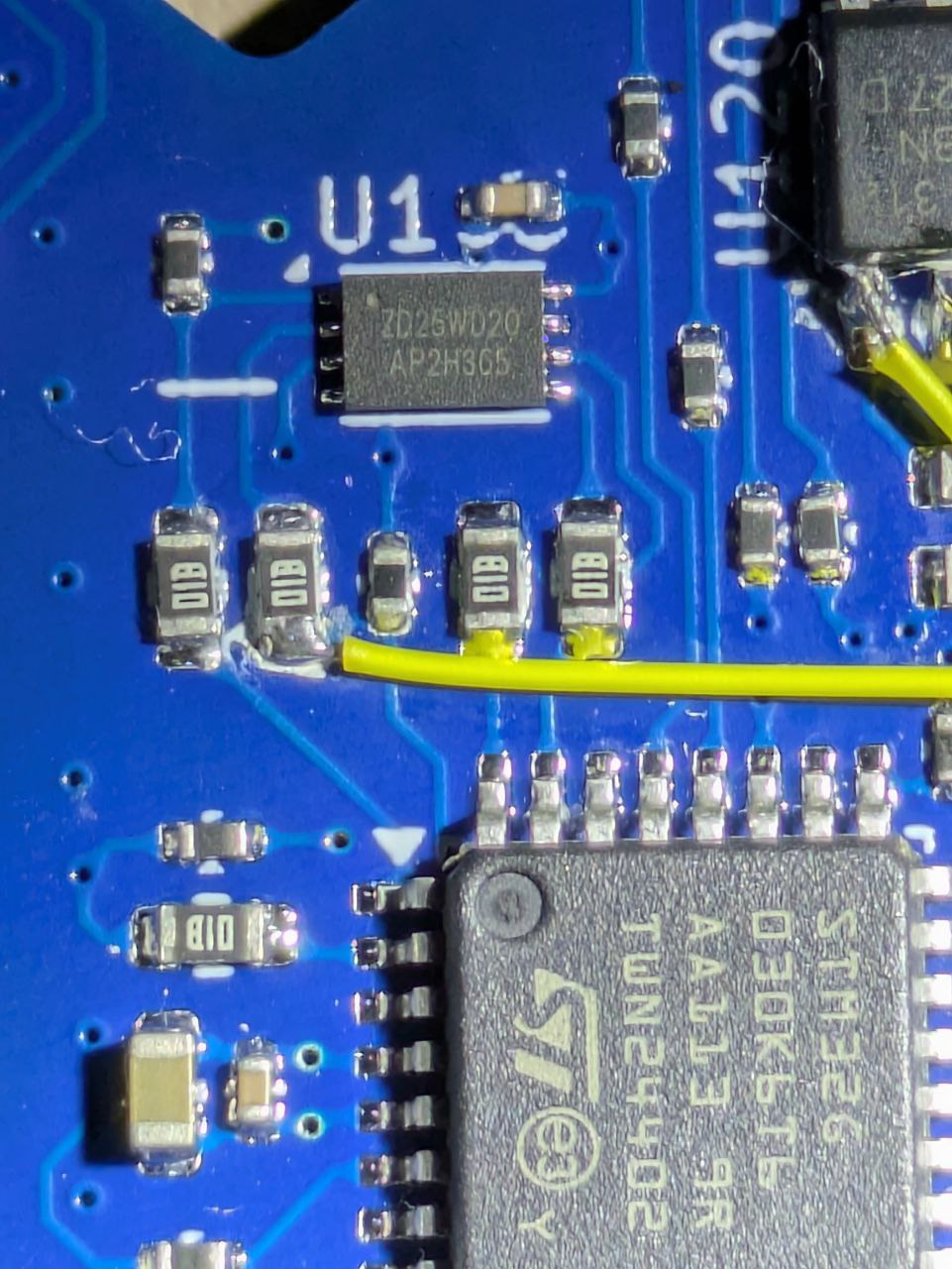
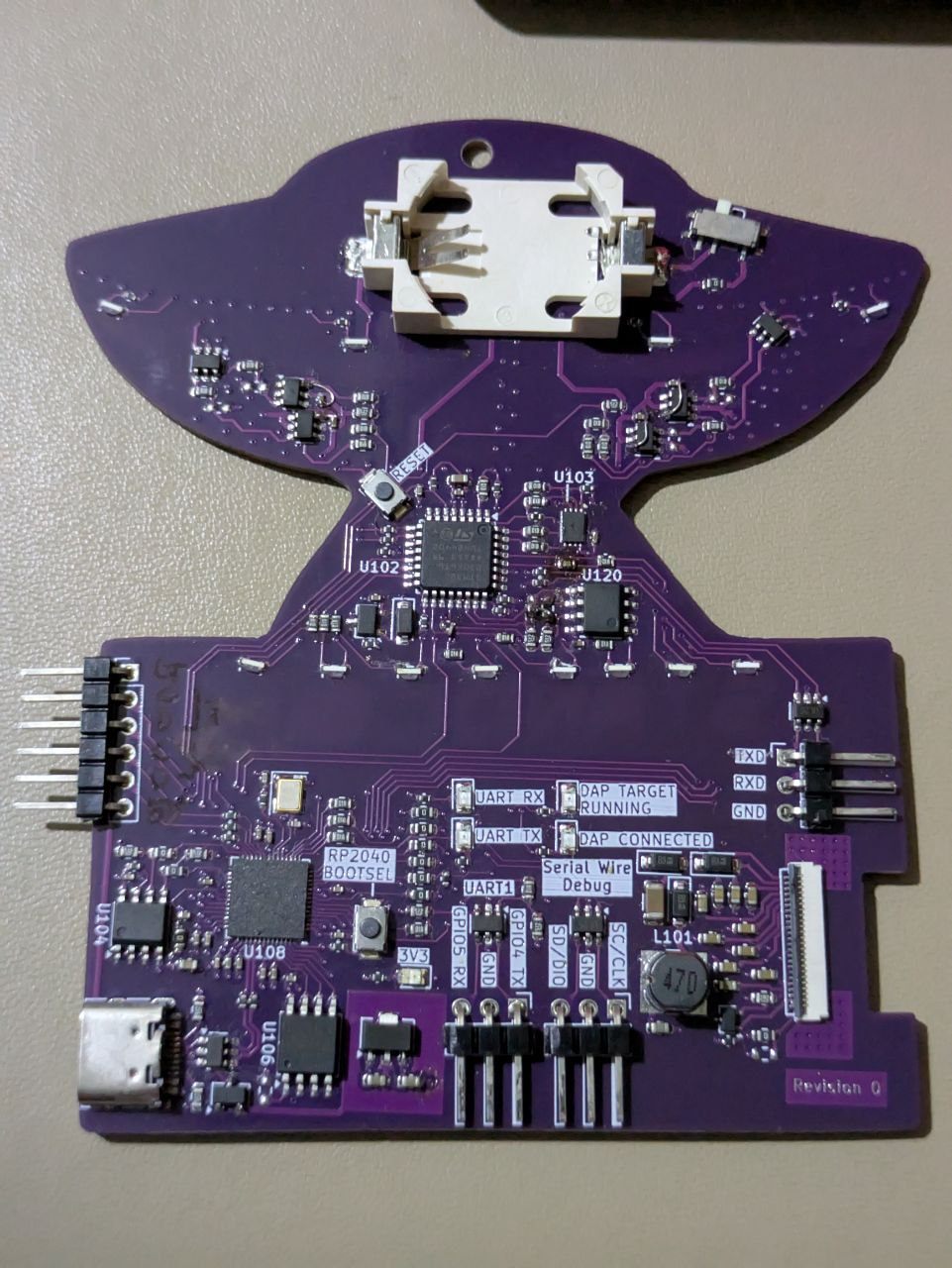
... a flag stored in the EEPROM (U104) connected to the RP2040.
We know its an EEPROM, but how is it connected to the RP2040?
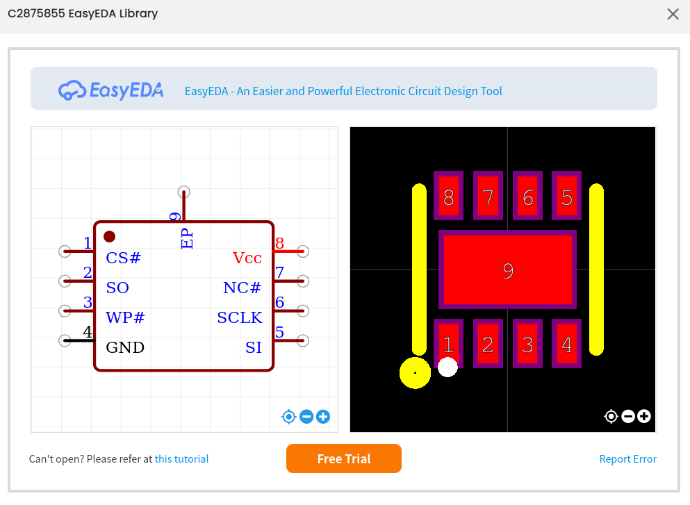
U104 is the 8 pin SOIC (package) next to the RP2040. Googling for 24C01 brings up datasheets for a EEPROM. Picking a random datasheet, we find the following pin-out:
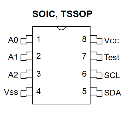
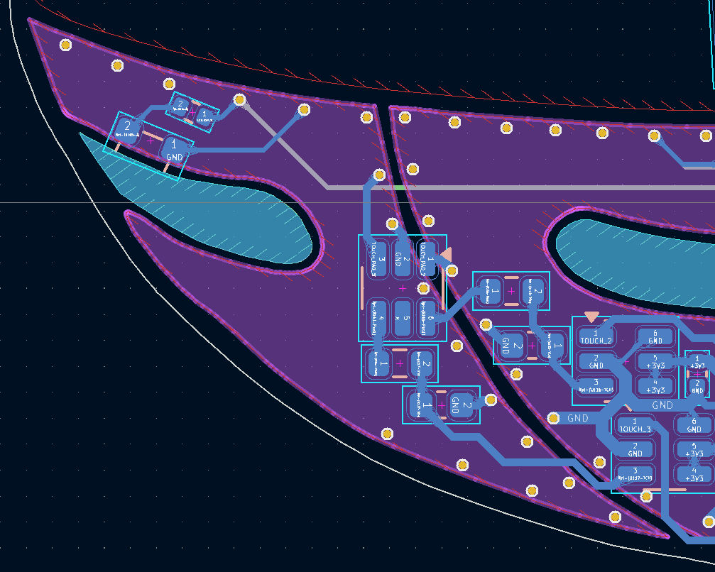
We see that pin 5 and 6 are SDA and SCL respectively, together forming a I2C bus, a common method of connecting a microcontroller to low speed devices. Tracing them visually through the 0-ohm resistors (thin red lines below on the left), we can follow them to the RP2040:
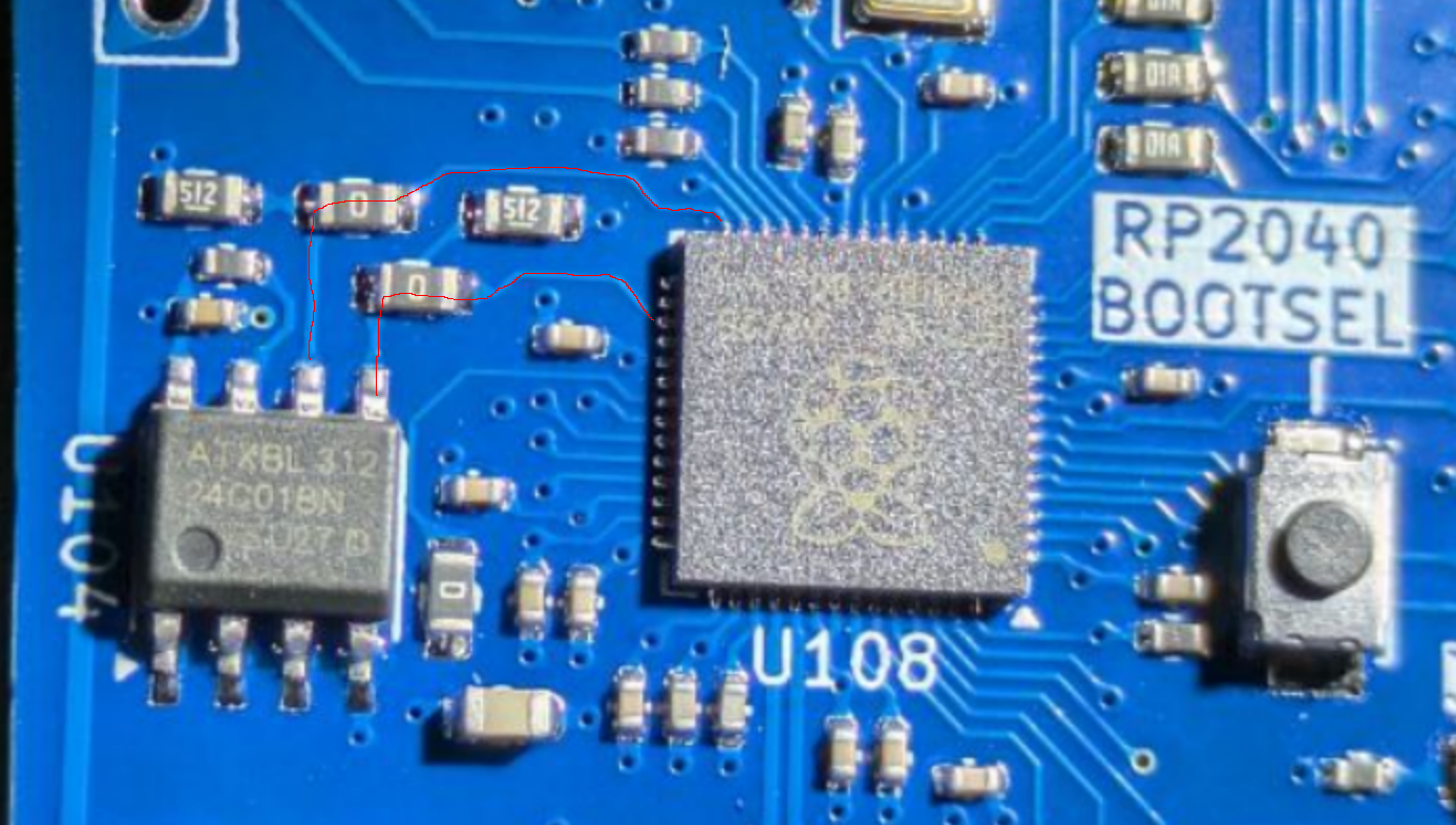
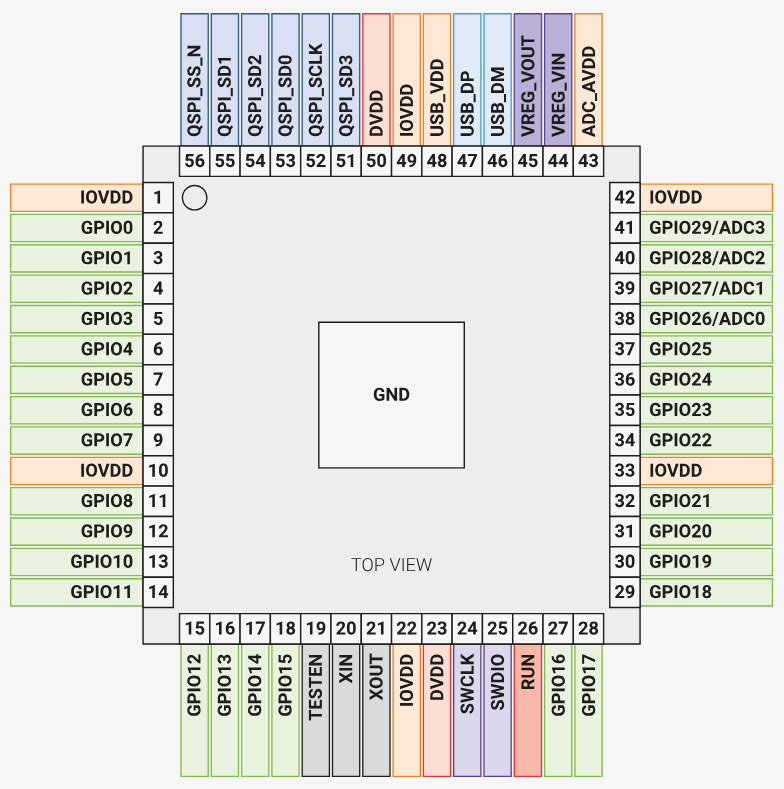
To find out which pins of the RP2040 are connected to the EEPROM, we take a look at the datasheet of the RP2040. Orienting with the pin 1 marker (bottom right U108 in the image above has a circular dot, matching the white arrow on the PCB) on the top left of the pin map below, we find that SDA is GPIO20, and SCL is GPIO17.
We can then dump the flag:
from machine import Pin, I2C, UART

EEPROM_ADDR = 80
i2c = I2C(0, scl=Pin(17), sda=Pin(20), freq=400000)

out = b""
out += i2c.readfrom_mem(EEPROM_ADDR, 0, 16)
out += i2c.readfrom_mem(EEPROM_ADDR, 16, 16)

print(out)
Simon Says
For some reason, even perfect memory dosen’t help here.
Author & Writeup: Aaron Ti
Challenge Files: chall_simon.py game.mpy
The game is split into 3 difficulties, where each difficulty requires the user to remember the sequence of the flashing lights in order, and repeat the sequence of the flashing lights using the buttons on the hardware badge. However, the buttons on the hardware badge are randomly mapped for every stage except for the first level. This requires the user to trial-and-error the buttons to discover the button mapping on runtime.
The 3 difficulties have differing maximum time and errors allowed. Thus, the participant will have to rewrite the script or reverse-engineer the logic behind the game further. One method is trivially changing the stdin input to the correct button sequence instead of requesting from the hardware buttons. This will result in the game solving itself. If the participant skips the level itself however, the game will segmentation fault during decryption due to how states are stored during runtime
By then, one will realize that the level_name value on the last level is some decrypted bytestring. By backtracking, the game computes its states via an imported micropython library function, which returns an int and stores it in an array. This states array is then passed into another imported micropython library function, which returns a dict containing game context values, as well as the decrypted bytestring on the last level.
As such, there is no need to reverse-engineer the imported micropython library, as we can bruteforce the two arguments for the abovementioned second micropython library function: the first argument as 5 for the last level, and the second argument as an array of ints (maximum array length of 4 since 4 levels passed).
from game import l

FLAG_FORMAT = b"flag{"
FOUND = set()

LIMIT = 0x3F

if __name__ == '__main__':
    for i in range(LIMIT):
        for j in range(LIMIT):
            for k in range(LIMIT):
                for p in range(LIMIT):
                    f_str = l(5, [i, j, k, p])["level_name"]
                    if FLAG_FORMAT in f_str and f_str not in FOUND:
                        print(f_str)
                        FOUND.add(f_str)
Connecting
Beep boop. There are two microcontrollers on the board, one directly accessible to the user over USB. Find a way to connect to the target and speak to its console.
Need a USB-Serial converter? The RP2040 is a pretty powerful microcontroller, why not just use it as one?
Quite a straightforward challenge - we see J106 with pins labelled TXD, RXD, GND, providing a serial bus to the device. Grabbing an external USB-Serial adapter would be the quickest method to attach to these, though to avoid requiring external hardware, the challenge was intended to be solved by using the exposed GPIO on the RP2040. Conveniently, GPIO4 and GPIO5 of UART1 are exposed, which can be connected to J106.
Note that in the nomenclature used in serial/UART communication, TX (transmit) of device A is to be connected to RX (receive) of device B, and vice versa. This can lead to some confusion and potential damage to the GPIO pins if the TX pins of both device A and device B are connected together since both pins would be trying to drive each other.
The logic levels (voltage level used to indicate HIGH) are also important - most devices now operate at 3.3V, though 5V was also a common level used not too long ago. In this particular instance, the STM32G030 happens to have 5V tolerant pins, though its worth measuring the voltage levels of a UART port before blindly connecting to it. Since a UART signal idles HIGH, measuring the TX pin should indicate the logic HIGH voltage. (Measuring the RX pin is also possible since most devices will have a pull-up on the RX pin to avoid floating the pin if nothing is connected to the UART port)
In this particular case, since both devices are on the same board and share a common ground plane, there isn't a need to connect the two GND pins, but this is necessary if talking to a off-board device powered separately.
➜  micropython-fs git:(main) ✗ mpremote mount .
Local directory . is mounted at /remote
Connected to MicroPython at /dev/ttyACM0
Use Ctrl-] or Ctrl-x to exit this shell
>
MicroPython ed71c1b8e-dirty on 2025-02-23; STANDCON 2025 Badge with RP2040
Type "help()" for more information.
>>> import uart_bridge

commands:
- flag
- login <password [a-zA-Z0-9_]+>
- pour
- validate

> flag
flag{d1d_y0u_sWap_ur_tx_rx_l1n3s}
Logging In
We will, we will rock you. Just kidding, no wordlists required.
[login] to the STM32 for your flag.
This challenge revolves around providing a password to the STM32:
> login foo
wrong password
The key bit here is to realise that the password validation is not constant time - validation takes longer as more of the more leading characters are correct. This allows the password to be bruteforced one character at a time:
import time
from machine import Pin, UART

# Ensure target UART connected to RP2040 GPIO4/5

uart = UART(1, baudrate=57600, tx=Pin(4), rx=Pin(5), timeout=100)


def guess(password):
    start = time.ticks_us()
    uart.write("login " + password + "\n")
    uart.readline()  # Dump echo
    res = uart.readline()
    elapsed = time.ticks_us() - start

    if "wrong" not in res:
        print(res)

    return elapsed


pw = ""

while True:
    highest = ("", 0)

    for c in "abcdefghijklmnopqrstuvwxyzABCDEFGHIJKLMNOPQRSTUVWXYZ0123456789_":
        elapsed = guess(pw + c)
        if elapsed > highest[1]:
            highest = (c, elapsed)

    print(f"new char {highest[0]} with elapsed={highest[1]}")
    pw += highest[0]
    print(pw)
In this case an artificial 3ms delay was added between each character to simplify exploitation of this side channel, though practically even strcmp is exploitable over the network.
sudo flag
This incident will be reported. To who you say?
Well, if you [validate] successfully for your flag, we can sweep all of this under the rug...
Taking a look at the provided source, we see that it does the following
- Read a couple of bytes from a I2C EEPROM
- Validate a checksum
- Validate that the data matches a specific format
The solution here of course is to write new data to the EEPROM matching the expected values for the flag - the challenge here is how to actually write data to the device.
The intended solution was to solder wires to the EEPROM's SDA and SCL lines (or to the resistors next to them) and connect them to the RP2040's GPIOs:
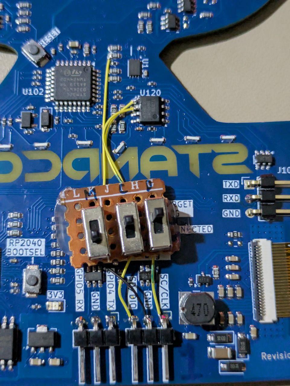
The EEPROM can then be written to:
import struct
import time
from machine import Pin, I2C

i2c = I2C(0, scl=Pin(13), sda=Pin(12), freq=100000)
print(f"I2C devices: {i2c.scan()}")

EEPROM_ADDR = 80
DATA_FORMAT = "<HBB"


def read():
    data = i2c.readfrom_mem(EEPROM_ADDR, 0, 4)
    print(struct.unpack(DATA_FORMAT, data))


def write():
    payload = struct.pack(DATA_FORMAT, 42, 200, 42 ^ 200 ^ 0xB3)
    i2c.writeto_mem(EEPROM_ADDR, 0, memoryview(payload))


write()
time.sleep(0.1)
read()
Note that while we were writing to the EEPROM, we actually left the STM32 running. In an actual application, the STM32 could write to the EEPROM while we were performing the attack and it would be smarter to hold the STM32 in reset so that there is no way it can drive the I2C bus. Performing such writes to other protocols (eg UART/SPI) also has more considerations because they are driven with push-pull IO.
I have been told that someone solved this challenge by continuously trying to write to the device and manually poking the SDA and SCL wires in by hand. This is an example of why I say that some of the scariest (in a great way) people I know are from the cybersecurity industry - while I would never try this as I would (and intended for people to) use proper tools to solder the wires down, there was technically absolutely nothing wrong with the approach and solved the challenge perfectly within the constraints.
An earlier revision of the challenge had the write-protect pin of the EEPROM driven to prevent writes to it, but it was removed to make the challenge easier. Perhaps I should have left that in to require three hands ;)
I just have to add a cautionary note here: please don't try this unless this is absolutely necessary. One's hand slipping and accidentally connecting the wire to the wrong point can cause damage - that these wires carried I2C signals (and thus configured for open-drain so that the RP2040 GPIO's would not source current) mitigated a significant portion of the risk, but shorting the lines to something like 3V3 is still a problem. The single wire might still also short adjacent pins of a integrated circuit together.
In this case there was also rudimentary protection on the badge itself - series resistors on the RP2040 GPIOs to limit how much fault current can flow, and current limiting on the USB power input would hopefully protect the upstream laptop in the case of catastrophic failure. Although USB ports should tolerate such over-current faults without any damage, it is not something I plan on ever testing on my own devices.
What's in the teapot?
The tea leaves in here are hiding something...
Grab a tea cup and [pour] out some tea from the STM32.
Taking a look at the provided source, we see that it does the following
- Read 16 bytes from a SPI device
- Use these 16 bytes to encrypt the flag
- Print the encrypted flag for the user
This challenge was inspired by the work done on sniffing Trusted Platform Module keys directly from the communications bus, and the obvious solution here is to grab a logic analyzer and sniff the 16 byte key from the SPI bus.
However, that requires equipment that we may not have (though PulseView compatible logic analyzers are sub-$20). So what can we do? The curious bit here is that the SPI protocol itself dosen't actually ensure that the slave device responded - it just clocks in the state of the MISO pin. We could desolder the device and the challenge code would be none the wiser. Of course, that would require more equipment.
The intended solution here was to short the MISO pin to GND, forcing the STM32 to always read 0 from the device, resulting in a key of sixteen 0s.
To identify the MISO pin, there are two approaches: the first is to identify the SPI device:
Searching ZD25WD20 brings up the following (well, my results are for the Chinese version at szlcsc, but I happen to know that the English site has the same:
Unfortunately the datasheet in this case dosen't actually list the specific package that is on the board, but only the larger variants:
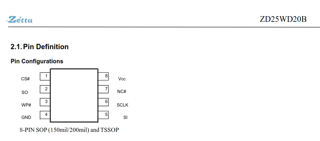
We can however, keep poking at the same page and we get the following (in hindsight, the SOP, TSSOP and USON-8 that we are using all have the same pin-outs, though this is not safe to assume in general.
And with that, soldering a wire between pin 2 and GND somewhere on the board will result in a all zero key:
You swirl the teapot before pouring out...

ac6a42ada694872b2de61be87f1d001a4aaf5cc06afbaf2c01d244698cdb8533
The encryption routine used in the code is identifiable as the Tiny Encryption Algorithm by searching for the magic constant, and the corresponding decryption routine will result in the flag:
import ctypes


enc_flag = "ac6a42ada694872b2de61be87f1d001a4aaf5cc06afbaf2c01d244698cdb8533"


def decipher(v, key):
    NUM_ROUNDS = 32
    v0, v1 = [ctypes.c_uint32(x) for x in v]
    delta = 0x9E3779B9
    sum = ctypes.c_uint32(delta * NUM_ROUNDS)

    for _ in range(NUM_ROUNDS):
        v1.value -= (((v0.value << 4) ^ (v0.value >> 5)) + v0.value) ^ (
            sum.value + key[(sum.value >> 11) & 3]
        )
        sum.value -= delta
        v0.value -= (((v1.value << 4) ^ (v1.value >> 5)) + v1.value) ^ (
            sum.value + key[sum.value & 3]
        )

    return [v0.value, v1.value]


out = b""
for i in range(0, len(enc_flag), 16):
    chunk = enc_flag[i : i + 16]
    v = [
        int.from_bytes(bytes.fromhex(chunk[0:8]), "little"),
        int.from_bytes(bytes.fromhex(chunk[8:16]), "little"),
    ]

    dec = decipher(v, [0] * 4)

    out += dec[0].to_bytes(4, "little")
    out += dec[1].to_bytes(4, "little")

print(out)
Board Design
Building this badge was quite the adventure, though it went far far better than I expected.
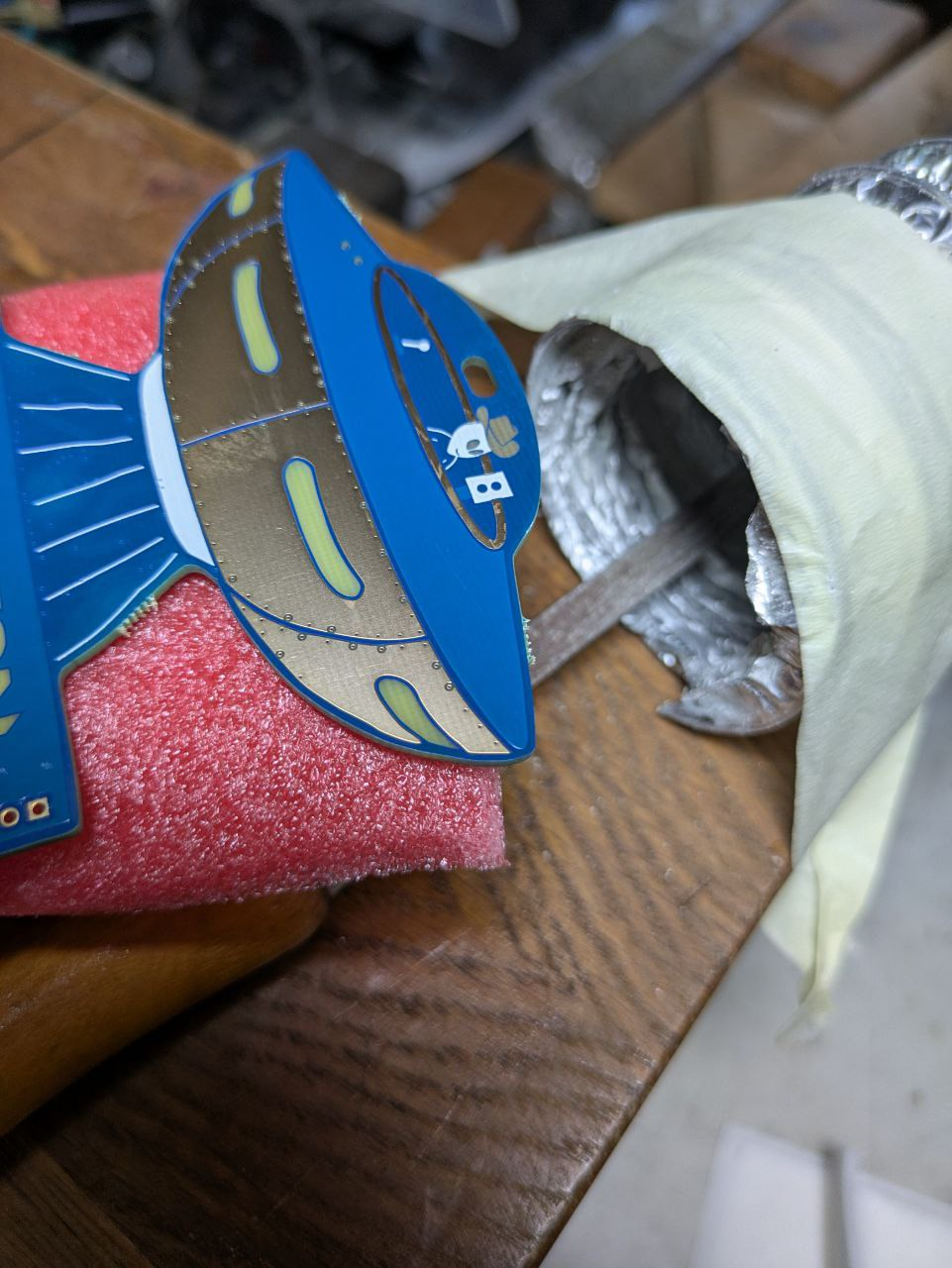
I spent a couple of weeks faffing around in Inkscape trying to draw something presentable as a badge design before giving up and just 3D-modelling the UFO I envisioned then tracing it:

Two design objectives were to include a couple of capacitive touch pads and the E-ink screen. The decision was made early on to use ENIG as a surface finish, so exposing a couple of copper pours here so that they would be gold colored was the simple solution. Though this is probably not ideal from a ESD perspective since humans would be touching these pads (humans likely walking around on carpet), dropping a couple of ESD diodes behind seemed good enough to handle this in theory.
KiCad imported the design cleanly and the relevant bits were converted into layers to take advantage of the colors and shades made possible by (ab)using the silk screen (white), solder mask (purple initially, then blue) over copper (lighter purple/blue), solder mask over bare substrate (darker purple/blue), bare copper (gold) and bare substrate (yellow-ish).
The LEDs were a significant challenge too: I wanted all components on the back but I also wanted LEDs visible from the front. Although reverse-mounted LEDs exist, they all seemed to be designed to mount into a hole in the PCB, rather than sitting flush on the PCB:

I didn't like the idea of punching holes all over the board just for LEDs, so I opted for side-mounted LEDs shining through the board. These were of course sub-optimal - the LEDs were not designed for this, but seemed good enough™.
Routing the board was a a nice change from my usual functionality-over-form designs, while this was form-over-functionality.
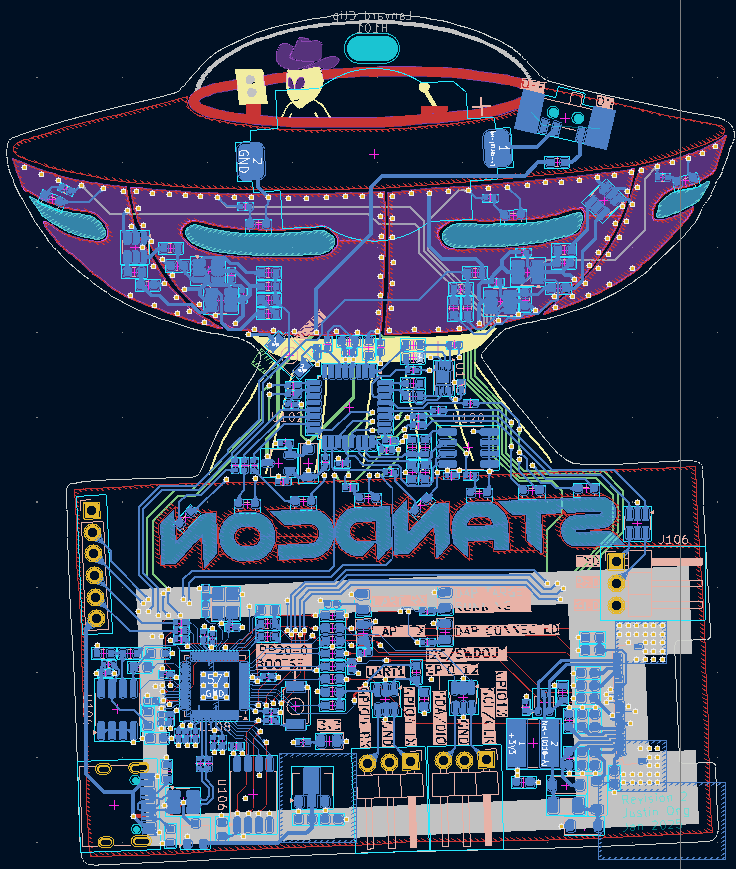
The goal of not dropping vias through the capacitive touch pads to keep them nice continuous gold pads resulted in a row of vias as "rivets" for the UFO's panels:
Of course I managed to transpose the I2C lines between the STM32 and the EEPROM, but I was saved by the 0-ohm jumpers sprinkled liberally through the board. I also managed to flip the pin-out for the FPC connector to the E-ink screen, though testing could still be done because the FPC connector was double sided and the screen just faced the wrong way.
In the interest of not having to rework the final batch, a second revision was built to ensure that the changes were correct and the design had full functionality, and they did!
Things were going too well and this time, instead of more work on components, I somehow didn't specify my de-panelisation requirements correctly and had six sharp, ugly mousebites on the badges to get rid of. Fiberglass dust is nasty and annoying to deal with.
All that was left was to test and program the whole batch:
- Power up with a lab power supply and check for nominal current consumption
- Connect to PC, flash RP2040 over USB, flash STM32 over ST-Link
- Check that touch pads worked
- Test IO, communication to peripherals
- Set up peripherals with challenge
- Redraw E-ink screen
Of this test procedure, only one failure was observed where the RP2040 failed to enumerate over USB - reworking it solved it with no further issues.
There was also initial mention of 8 flags, but astute readers might have noticed that I only listed 7 above. The last challenge was TODO and added at the last minute, I made the standard off-by-one error on the STM32:
if (flags_solved == 1) {
  // pattern 1
} else if (flags_solved == 2) {
  // pattern 2
}
  ...
} else if (flags_solved == 7) {
  ...
}
... and if 8 flags were marked solved ... nothing lights up. The if statement dosen't handle the condition. Oops.
If you do want the last flag, its embedded in the firmware of the RP2040. And if you do accidentally submit all 8 flags and have no LEDs on your badge, you can reset the solve state by submitting the flag CTRL_led_reset. Submit just 7 flags next to have the badge be full lit-up.
I hope you had fun and I'ld love to hear your feedback on the badge and the challenges! Part of the challenge initially was not knowing what kind of skill level to target the badge at - while someone familiar with hardware would blaze through these challenges, tying it back to STANDCON's goal of making cybersecurity accessible felt like a good starting point. Perhaps more interesting challenges next time? I have been itching for an excuse to play with the ultra-low cost Linux-capable system-on-chips...